Separation and promotion of integration
Solid-liquid separation, grease collection and sewage lifting are combined to facilitate centralized arrangement in the equipment room.


When the temperature rises, air and other dirt are added, and it is very easy to form highly irritating fatty acids. This fatty acid can also cause serious damage to drainage, water supply equipment and pumping stations.
Separating grease from wastewater and professionally treating it benefits the environment. Municipal drainage regulations clearly stipulate that any material that would damage the public sewer network must not be discharged into it. It is especially suitable for the catering industry to produce wastewater containing grease.
Grease is lighter than water and cannot dissolve in water. It will be deposited on the pipe wall and stick to other dirt, blocking the pipe. This is true both in homes and in public sewer systems where grease accumulates. Impairing water quality, causing damage and costly repairs.
Slag removal, oil removal and liquid level improvement are connected in an orderly manner, and oily kitchen wastewater is processed in stages.
Oily soup, leftover food residue, etc. enter the equipment along with the catering drainage pipeline.
Catering drainage pipeline → equipment water inletThe grid intercepts solid residues, and the spiral conveying structure sends the residues into the collection bucket.
Solid-liquid separation bin → Residue collection barrelThe difference in density between oil and water is used to separate the grease, and then it is collected and entered into the oil collection barrel through the oil drain pipeline.
Oil-water separation unit → oil collection barrelThe separated sewage enters the lifting bin, starts and stops the water pump controlled by the liquid level, and is lifted and discharged through the water outlet pipe.
Sewage lifting bin → water outlet pipelineMaintain the fluidity of grease and cooperate with the collection and discharge of grease.
The cleaning structure cooperates with the slag removal mechanism to facilitate continuous operation.
The control system manages each unit in a unified manner, making it easy to check the equipment status.
There are two layout methods: built-in pump and external pump, which are selected according to the processing flow rate and lifting head. The flow rate covers 15–75 m³/h. The corresponding dimensions, water inlet and outlet interfaces and power supply parameters are provided in the table.
Listed according to pages 45-46 of the brochure · You can slide horizontally to view the complete parameters
| Device model | trafficm³/h | Liftm | PowerkW | Overall dimensions L × W × Hmm | Water inlet D1DN | Water outlet D2DN | VoltageV |
|---|---|---|---|---|---|---|---|
| PGI1515-300 | 15 | 15 | 6.75 | 2119 × 1300 × 1790 | DN100 | DN50 | 380 |
| PGI1522-300 | 15 | 22 | 8.15 | 2119 × 1300 × 1790 | DN100 | DN50 | 380 |
| PGI2015-300 | 20 | 15 | 8.15 | 2876 × 1320 × 1790 | DN100 | DN50 | 380 |
| PGI2022-300 | 20 | 22 | 9.75 | 2876 × 1320 × 1790 | DN100 | DN65 | 380 |
| PGI2515-300 | 25 | 15 | 8.15 | 3300 × 1500 × 1790 | DN150 | DN50 | 380 |
| PGI2522-300 | 25 | 22 | 9.75 | 3300 × 1500 × 1790 | DN150 | DN65 | 380 |
| PGI3015-300 | 30 | 15 | 9.75 | 3550 × 1500 × 1790 | DN150 | DN65 | 380 |
| PGI3022-300 | 30 | 22 | 11.75 | 3550 × 1500 × 1790 | DN150 | DN65 | 380 |
| PGI3515-300 | 35 | 15 | 9.75 | 3800 × 1500 × 1790 | DN150 | DN65 | 380 |
| PGI3522-300 | 35 | 22 | 11.75 | 3800 × 1500 × 1790 | DN150 | DN65 | 380 |
| PGI4015-300 | 40 | 15 | 9.75 | 4050 × 1500 × 1790 | DN150 | DN65 | 380 |
| PGI4022-300 | 40 | 22 | 11.75 | 4050 × 1500 × 1790 | DN150 | DN65 | 380 |
| PGI4515-300 | 45 | 15 | 11.7 | 4300 × 1500 × 1790 | DN150 | DN65 | 380 |
| PGI4522-300 | 45 | 22 | 14.75 | 4300 × 1500 × 1790 | DN150 | DN65 | 380 |
| PGI5015-300 | 50 | 15 | 11.75 | 4500 × 1500 × 1790 | DN150 | DN65 | 380 |
| PGI5022-300 | 50 | 22 | 14.75 | 4500 × 1500 × 1790 | DN150 | DN65 | 380 |
| PGI5515-300 | 55 | 15 | 14.75 | 4800 × 1500 × 1790 | DN150 | DN80 | 380 |
| PGI5522-300 | 55 | 22 | 18.75 | 4800 × 1500 × 1790 | DN150 | DN80 | 380 |
| PGI6015-300 | 60 | 15 | 11.75 | 5050 × 1500 × 1790 | DN150 | DN80 | 380 |
| PGI6022-300 | 60 | 22 | 18.75 | 5050 × 1500 × 1790 | DN150 | DN80 | 380 |
| PGI6515-300 | 65 | 15 | 14.75 | 5300 × 1500 × 1790 | DN200 | DN80 | 380 |
| PGI6522-300 | 65 | 22 | 18.75 | 5300 × 1500 × 1790 | DN200 | DN80 | 380 |
| PGI7515-300 | 75 | 15 | 18.75 | 5800 × 1500 × 1790 | DN200 | DN80 | 380 |
| PGI7522-300 | 75 | 22 | 18.75 | 5800 × 1500 × 1790 | DN200 | DN80 | 380 |
L is the length of the equipment, W is the width of the equipment, and H is the height of the equipment; the interface is marked according to the nominal diameter DN. The power is the value marked on the original color page, and the specific equipment configuration is confirmed based on the processing capacity, lifting head and on-site space.
Listed according to pages 49-50 of the brochure · You can slide horizontally to view the complete parameters
| Device model | trafficm³/h | Liftm | PowerkW | Overall dimensions L × W × Hmm | Water inlet D1DN | Water outlet D2DN | VoltageV |
|---|---|---|---|---|---|---|---|
| PGI1515-300W | 15 | 15 | 6.75 | 2119 × 1300 × 1790 | DN100 | DN50 | 380 |
| PGI1522-300W | 15 | 22 | 8.15 | 2119 × 1300 × 1790 | DN100 | DN50 | 380 |
| PGI2015-300W | 20 | 15 | 8.15 | 2876 × 1320 × 1790 | DN100 | DN50 | 380 |
| PGI2022-300W | 20 | 22 | 9.75 | 2876 × 1320 × 1790 | DN100 | DN65 | 380 |
| PGI2515-300W | 25 | 15 | 8.15 | 3300 × 1500 × 1790 | DN150 | DN50 | 380 |
| PGI2522-300W | 25 | 22 | 9.75 | 3300 × 1500 × 1790 | DN150 | DN65 | 380 |
| PGI3015-300W | 30 | 15 | 9.75 | 3550 × 1500 × 1790 | DN150 | DN65 | 380 |
| PGI3022-300W | 30 | 22 | 11.75 | 3550 × 1500 × 1790 | DN150 | DN65 | 380 |
| PGI3515-300W | 35 | 15 | 9.75 | 3800 × 1500 × 1790 | DN150 | DN65 | 380 |
| PGI3522-300W | 35 | 22 | 11.75 | 3800 × 1500 × 1790 | DN150 | DN65 | 380 |
| PGI4015-300W | 40 | 15 | 9.75 | 4050 × 1500 × 1790 | DN150 | DN65 | 380 |
| PGI4022-300W | 40 | 22 | 11.75 | 4050 × 1500 × 1790 | DN150 | DN65 | 380 |
| PGI4515-300W | 45 | 15 | 11.7 | 4300 × 1500 × 1790 | DN150 | DN65 | 380 |
| PGI4522-300W | 45 | 22 | 14.75 | 4300 × 1500 × 1790 | DN150 | DN65 | 380 |
| PGI5015-300W | 50 | 15 | 11.75 | 4500 × 1500 × 1790 | DN150 | DN65 | 380 |
| PGI5022-300W | 50 | 22 | 14.75 | 4500 × 1500 × 1790 | DN150 | DN65 | 380 |
| PGI5515-300W | 55 | 15 | 14.75 | 4800 × 1500 × 1790 | DN150 | DN80 | 380 |
| PGI5522-300W | 55 | 22 | 18.75 | 4800 × 1500 × 1790 | DN150 | DN80 | 380 |
| PGI6015-300W | 60 | 15 | 11.75 | 5050 × 1500 × 1790 | DN150 | DN80 | 380 |
| PGI6022-300W | 60 | 22 | 18.75 | 5050 × 1500 × 1790 | DN150 | DN80 | 380 |
| PGI6515-300W | 65 | 15 | 14.75 | 5300 × 1500 × 1790 | DN200 | DN80 | 380 |
| PGI6522-300W | 65 | 22 | 18.75 | 5300 × 1500 × 1790 | DN200 | DN80 | 380 |
| PGI7515-300W | 75 | 15 | 18.75 | 5800 × 1500 × 1790 | DN200 | DN80 | 380 |
| PGI7522-300W | 75 | 22 | 18.75 | 5800 × 1500 × 1790 | DN200 | DN80 | 380 |
L is the length of the equipment, W is the width of the equipment, and H is the height of the equipment; the interface is marked according to the nominal diameter DN. The power is the value marked on the original color page, and the specific equipment configuration is confirmed based on the processing capacity, lifting head and on-site space.
The front view, top view and dimensional leads in the original color page are retained, and you can click to view the high-resolution image. The L, W, H and D1, D2 values of the corresponding models are shown in the selection table above.
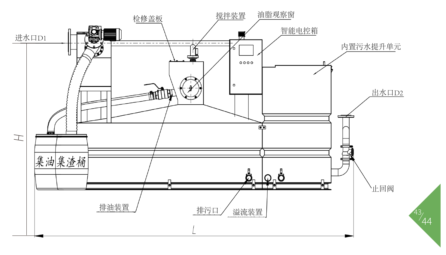
L/H appearance marking, water inlet D1, water outlet D2 and main functional components
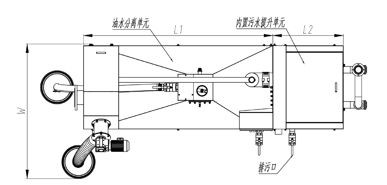
W overall width and L1, L2 unit partition labeling
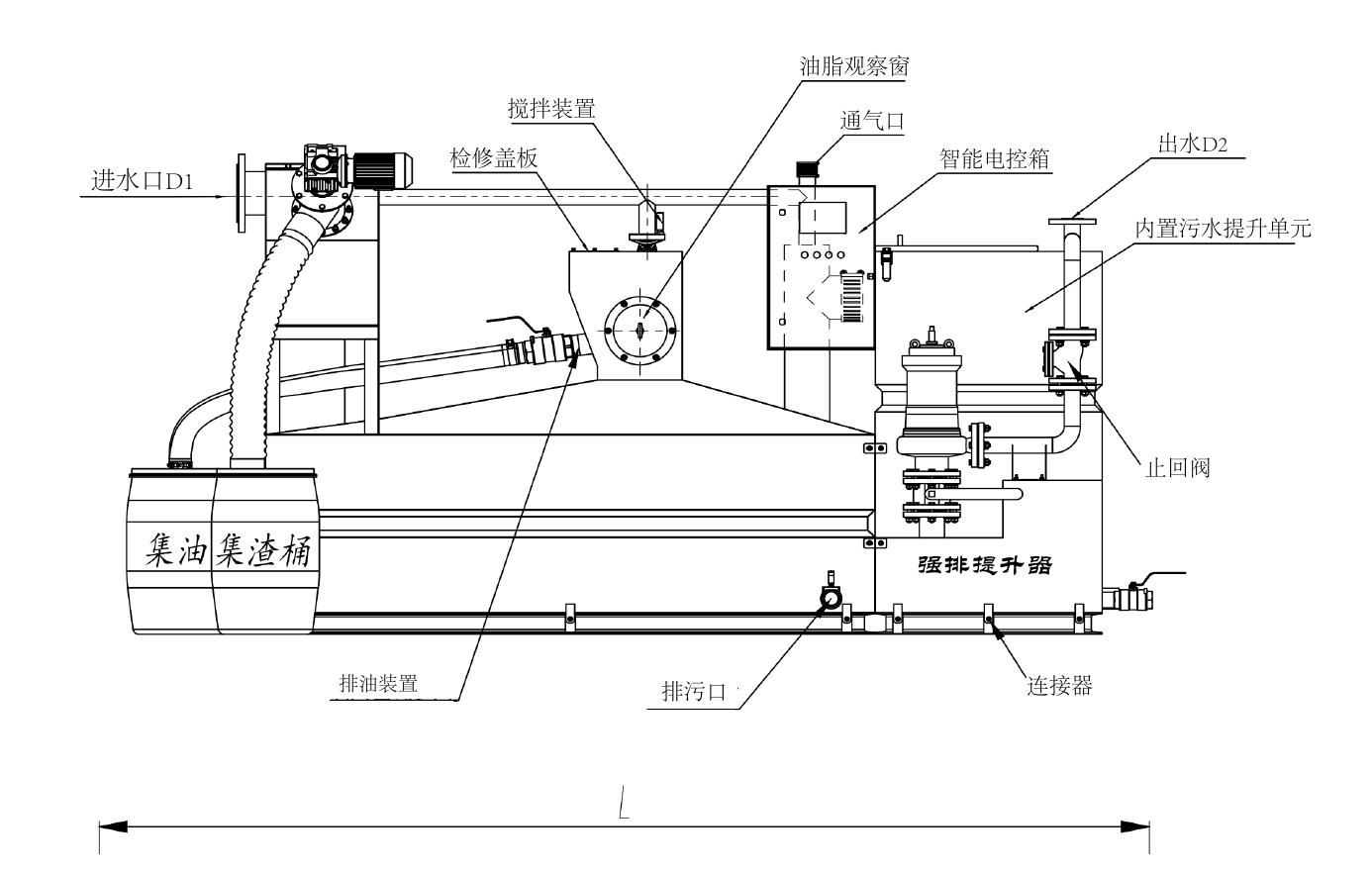
External pump unit layout, L length marking and water inlet and outlet interfaces
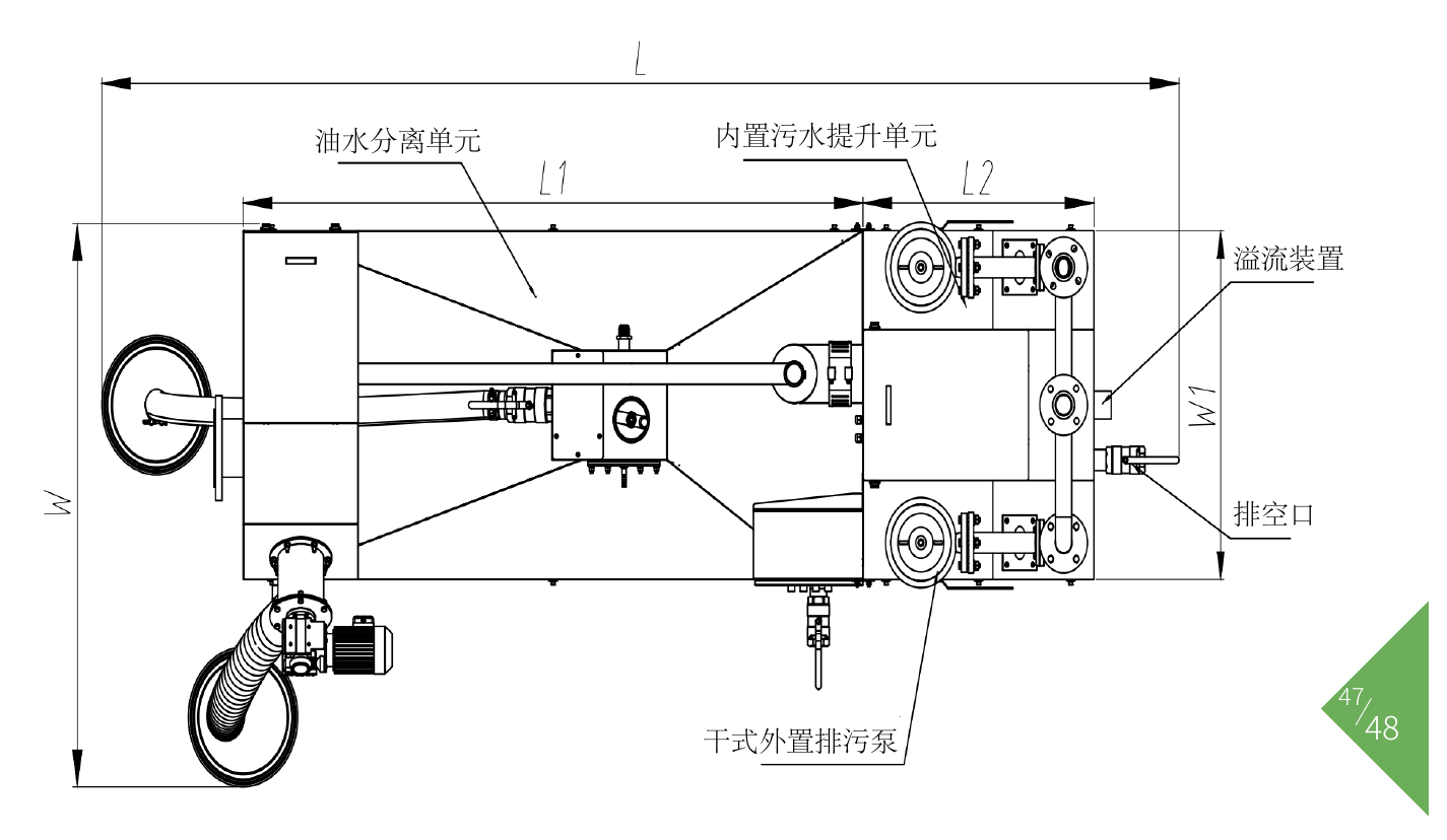
W Total width and layout relationship of oil-water separation and sewage lifting units
The drawings show the general appearance shown in the color page. L1 and L2 are used to identify the partition length of the equipment unit. The model-by-model values are not listed on the brochure; the specific partition size and connection location are subject to the project confirmation drawing.
High-efficiency active filtration and separation technology, Jingchang intelligent control cleaning system, dual-pump intelligent design


From the separation mechanism to the double-pump lifting, from equipment layout to daily maintenance, we pay attention to every operation link.
Solid-liquid separation, grease collection and sewage lifting are combined to facilitate centralized arrangement in the equipment room.
The spiral conveyor and filter cleaning structure work together to reduce daily manual cleaning.
The rear-end lifting chamber of the built-in pump series is equipped with dual pumps, combined with liquid level control start and stop, to facilitate equipment operation and management.
The stainless steel box is equipped with an access cover, and the pipeline interfaces are centrally arranged to facilitate inspection and maintenance.


