


 Back

When selecting Compact Direct-Connect Water Booster Station, you can't just look at "how tall the building is" or "how big the motor is." How much head the equipment needs to supplement depends on the dynamic water head that the inlet can provide, the height difference at the most unfavorable point, terminal water requirements and pipeline loss. The following takes a model of EPANEL YP-S1 as an example to illustrate the process from field data to preliminary screening of samples to debugging and verification.
A. Measure the four basic conditions clearly
Design flow:It is determined based on the service objects, water appliances, usage period and simultaneous water use conditions, and is verified based on the actual measured data in the early stage of the renovation project. The reference number of water supply households in the equipment sample can only assist in estimation and cannot directly replace the design flow rate.
Available water head at the entrance:Use the lowest dynamic pressure confirmed to be available that corresponds to the design flow rate. The static pressure read when the pump is stopped or when water consumption is low cannot directly replace the inlet pressure during peak operation.
Worst point requirements:Clarify its height difference relative to the pumping station, as well as the minimum residual pressure required by the water appliance or design documents. The terminal requirements for different uses may be different, and it is not appropriate to apply an unverified uniform value.
Pipeline loss:According to the calculated flow rate, local and along-process losses such as pipeline length, pipe diameter, elbows, valves, water meters, and filters should be considered, and it should be clear whether these losses are located before or after the pressure measurement point to avoid omissions or double counting.
B. Use unified water head unit to calculate the required pressure increase
Taking the reference position of the pumping station as the benchmark, converting the pressure into meters of water column, and temporarily ignoring the inlet and outlet velocity and head differences for the convenience of explanation, it can be written as:
HSupercharge = Δz + HTerminal residual pressure + hloss − HEntrance available
Among them, Δz is the height difference between the most unfavorable point and the pumping station. If the available water head at the inlet has been measured at the pump suction inlet, the loss already reflected in the pressure reading upstream of the measuring point should not be deducted again; if it is taken from other locations, it needs to be converted to the same reference position first.
Assume that the calculation conditions for a renovation project are as follows. These numbers are for demonstration purposes only and are not general design parameters for all homes.
| Calculation project | Example values | Value description |
|---|---|---|
| Design flow Q | 6 m³/h | Assumptions for completed project water demand calculations |
| Height difference of the most unfavorable point Δz | 18 m | Relative pumping station reference position |
| Required residual pressure head at the end | 10 m | Design requirements in example, non-uniform limits |
| Loss from the pumping station to the most unfavorable point | 5 m | Calculated as Q = 6 m³/h |
| Minimum dynamic inlet head | 12 m | Converted to available value at pump suction |
From this we get the required boosting head:18 + 10 + 5 − 12 = 21 m. The required water head at the corresponding outlet is 33 m. According to the common approximate conversion of water, 21 m water column is about 0.206 MPa, and 33 m water column is about 0.324 MPa. The former is the pressure difference that the water pump needs to supplement, and the latter is the outlet demand in this example. The two cannot be mixed.
C. Check the performance table instead of just looking at the numbers in the model number
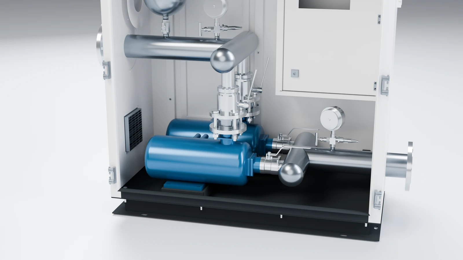
In the EPANEL product information,50YP-S1-6-22-0.75x2 Corresponds to the following equipment flow and lift points:
| Equipment flow rate Q (m³/h) | 2 | 3 | 4 | 5 | 6 |
|---|---|---|---|---|---|
| Corresponding head H (m) | 29 | 27 | 26 | 24 | 22 |
When Q = 6 m³/h, H = 22 m in the table, which is 1 m more than the 21 m calculated in the example, so it can enter the preliminary screening candidate.This 1 m nominal margin does not mean that the final selection has been established.It is also necessary to check the working range with the complete performance curve, review the inlet fluctuations, filter operating losses and operating combinations; calculate the available NPSH and compare it with the necessary NPSH and required margin provided by the manufacturer. When conditions change, the model or system plan should be recalculated.
The supporting water pumps for this model are YPDS32-4-26, the total number of installations is 2, 0.75 kW is the rated power of a single pump, and the control cabinet model is YPK702QB-1.5S1. Q in the equipment table is the corresponding working condition flow of the equipment, which cannot be multiplied by 2 just because there are two pumps; the motor nameplate power cannot replace the actual operating power or annual power consumption of the entire equipment.
D. Both the minimum value of the inlet and the maximum pressure of the system must be checked.
Selection depends not only on whether it can be supplied during peak hours, but also on whether it can withstand low water consumption, high inlet pressure, and control abnormality boundaries. The inlet conditions, maximum outlet pressure, and allowable pressure of water pumps and pipeline valves should be checked separately, and anti-backflow and corresponding protection should be configured according to local access requirements.
The measuring points and setting values of the constant voltage control should be consistent with the reference position used in the calculation. If it is necessary to consider the pressure compensation that changes with the flow rate, it must be set in combination with the characteristics of the pipe network and the functions of the control system. It cannot be adjusted arbitrarily in order to pursue "more pressure", nor can it only use the lowest frequency of the frequency converter to judge whether the pump set matches.
E. Verification of installation and commissioning using working condition records
Before installation, check the foundation load-bearing, drainage, maintenance and door opening space, and check the water inlet and outlet diameter, power supply, protective grounding and construction drawings. Before putting into use, pipeline cleaning and disinfection, sensor and instrument verification, and necessary acceptance must be completed according to project requirements. The completion of cabinet installation will not replace system delivery.
Debugging should cover working conditions such as small flow, normal flow, peak flow, working pump rotation and failover, and record inlet and outlet pressures, most unfavorable point pressure, operating frequency, current, number of starts and stops, and alarm information. Low pressure, water shortage and overpressure protection should be verified according to validated methods and cannot be tested through operations that actually harm the water supply network.
Only by forming a set of traceable data such as calculation sheets, final models, control parameters, debugging records and maintenance requirements can we judge whether the equipment is operating within the design boundaries and retain the basis for subsequent troubleshooting of pressure fluctuations, frequent starts and stops or abnormal energy consumption.
For principles and application conditions, please refer to:Compact Direct-Connect Water Booster Station operating principle: superimposed pressure boosting and application boundaries. For complete product configuration, seeEPANELCompact Direct-Connect Water Booster Station。
Data basis and further reading
The model and performance points are based on the EPANEL YP-S1 product brochure and specification model information; the calculations in this article are method demonstrations, and the actual selection is based on the project design and confirmed performance information.
Height difference, terminal pressure and pipeline loss of booster system · Effect of inlet pressure on booster selection