Back
Water supply flow
1–44m³/h
Determined by device model


YP-S1 / Overview
Provides a compact direct-connected booster solution for dispersed water use scenarios.
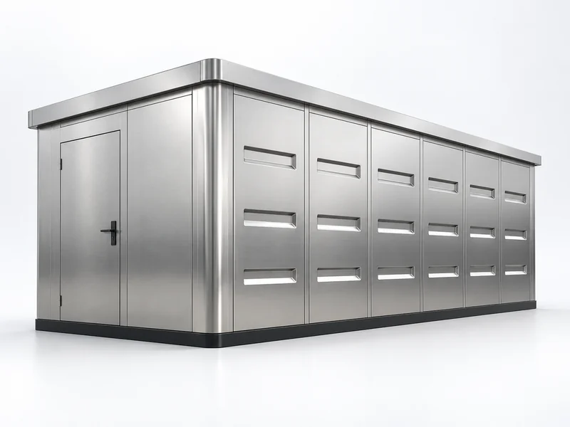
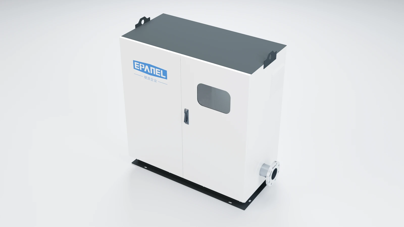
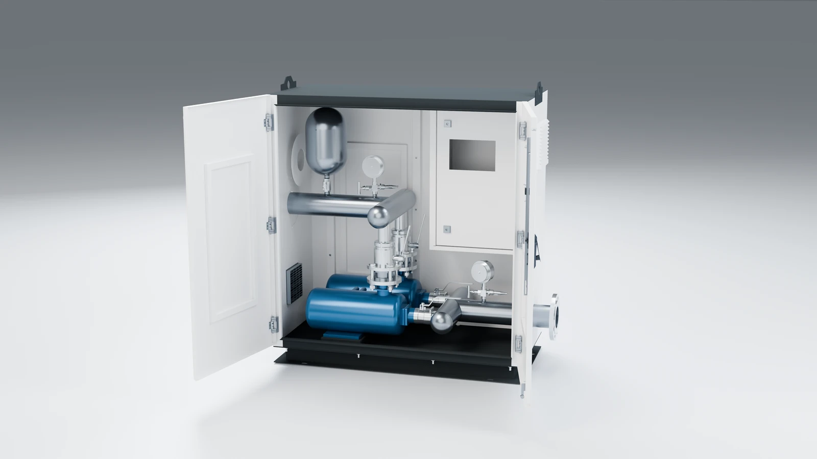
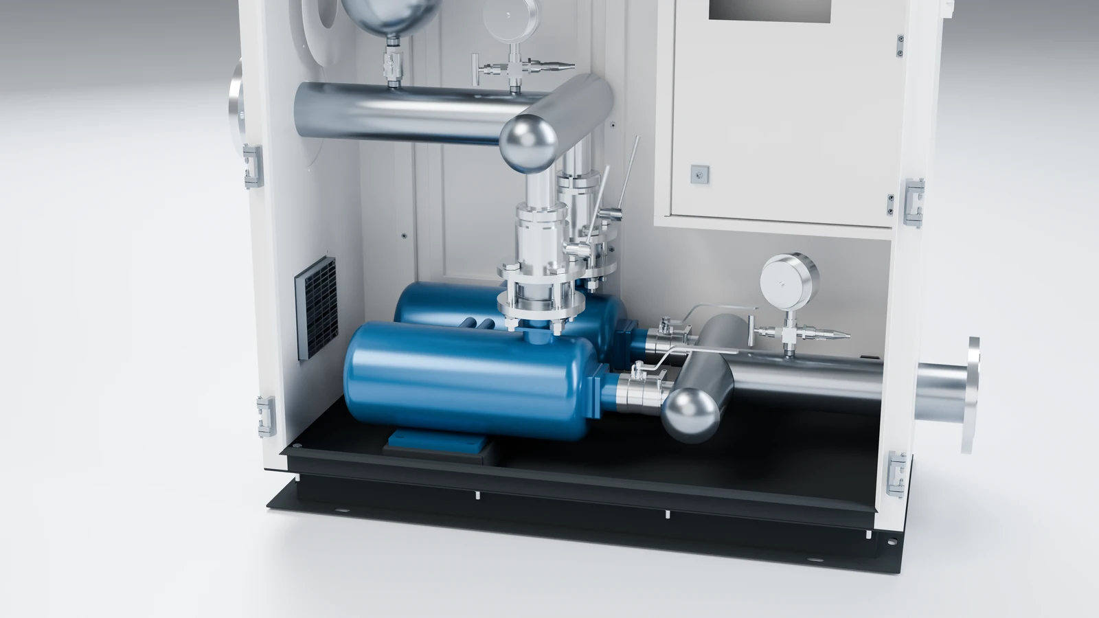
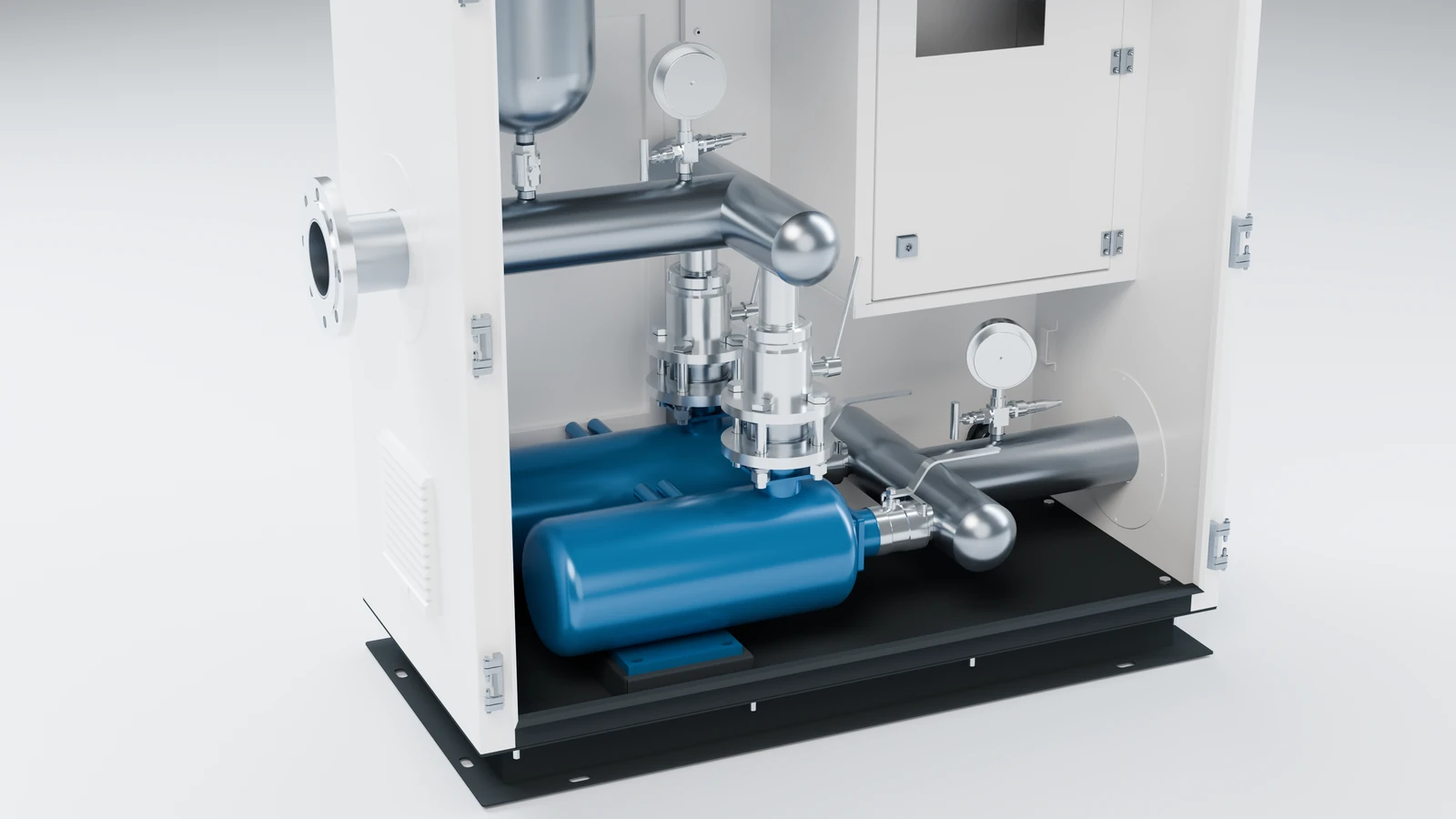
The YP-S1 series of micro direct-connected water supply pump stations are designed for rural self-built houses, villas, single buildings in old communities and urban and rural water supply renovation. The outdoor cabinet, horizontal centrifugal pump, pressure stabilizing tank, full frequency conversion control system, instruments and pipeline valves are integrated and arranged. It can not only be connected to the water supply pipe network to achieve superimposed water supply, but also be connected to the water tank to achieve regulated and pressurized water supply.
Micro integration / direct connection to pipe network / configuration on demand

1–44m³/h
Determined by device model
20–60mH₂O
Determined by device model
0–70℃
01 / OPERATING PRINCIPLE
Use pressure feedback to connect water inlet, pressurization and water use.
If you have a narrow screen, you can slide left or right to view the complete diagram.
The incoming water enters the equipment through the maintenance valve and filter, and the water inlet pipeline is connected to the pump unit.
The control system adjusts the water pump speed based on pressure feedback to match water demand; the water pump and frequency converter adopt a one-to-one full frequency conversion configuration.
The water output from the pump unit flows into the water outlet main pipe through the valve group, and cooperates with the pressure stabilizing tank and pressure instrument to supply water to the user pipe network.
The pressure signal is sent to the control cabinet to coordinate soft start and soft stop, operation monitoring and abnormal protection.
System connections are shown as illustrations. The direct connection solution needs to be confirmed based on water supply conditions and project design. The specific model, configuration and technical parameters are subject to the selection plan.
02 / APPLICATIONS
From individual buildings to the end of village and town pipe networks.
It is suitable for the water supply renovation of a single building and provides pressurized water supply based on the existing pipe network conditions.
For scattered residential and small-scale water use scenarios, equipment is selected according to flow rate and head.
It is used for local pressurization at the end of village pipe network and in urban and rural water supply construction.
It is suitable for pressurizing the pipe network of small high-rise residential buildings or pressurizing top-level users who supply water from roof water tanks.
Cabinet-type integrated layout can be installed outdoors, in corridors or on the roof according to site conditions.
When connected with the water tank, it can form a regulated and pressurized water supply scheme.
03 / CONTROL & PROTECTION
Focusing on water supply control, equipment protection and operation management.
Set the water supply control mode according to operating requirements, taking into account flow changes and pressure regulation.
Full frequency conversion speed regulation is used to match the operation of the pump unit with actual water demand.
Control the speed and start-stop process to reduce the impact of equipment start-up and stop on the water distribution pipe network.
Configure equipment protection for temperature and humidity conditions to ensure the control and operating environment.
Monitor the pressure of the pipeline network and provide protection against overpressure abnormalities.
Monitor water shortage conditions and provide water shortage protection for pump units.
Combined with anti-freeze control and optional insulation measures, it can adapt to low-temperature installation environments.
Connect to the user management platform through the Internet of Things module to support remote monitoring and operation and maintenance.
04 / PRODUCT ADVANTAGES
Integrate installation, use and maintenance into the design.
The two-pump cabinet is 900×450×1200mm, covering an area of about 0.405m²; the three-pump cabinet is 1200×600×1300mm, which is easy to install according to site planning.
The equipment and water distribution pipes are connected by flanges, and the overall cabinet layout facilitates transportation, takeover and installation organization.
The true-color touch screen cooperates with digital instruments to centrally view operating information; bus control and monitoring support diagnosis and early warning.
The frequency converter and the water pump are configured one-to-one, and through speed adjustment and soft start and soft stop, the pressure fluctuation during the start and stop process is reduced.
High carrier frequency conversion optimizes the voltage waveform, and cooperates with the sound-absorbing cotton in the cabinet and door frame sealing to suppress electromagnetic noise and sound leakage.
The IoT module supports the docking of multiple data centers and user platforms to facilitate centralized monitoring, alarming and operation management.
05 / SPECIFICATIONS
Water supply capacity, control configuration and working conditions.
06 / MODEL DESIGNATION
Use typical models to understand the equipment configuration.
50YP-S1-12-40-2.2×250Main pipe diameterYPEquipment seriesS1Product form12Model marked flow rate40Single pump lift2.2Single pump power×2Number of pumps07 / TECHNICAL DATA
Five groups of traffic levels and twenty device configurations.
The head H in the table corresponds to the flow rate Q in each column; the narrow screen can slide left and right to view the complete parameters.
| serial number | Device model | Control cabinet model | Horizontal centrifugal pump model | Number of pumps | Single pump powerkW | Corresponding head H (m) | Net weightkg | ||||
|---|---|---|---|---|---|---|---|---|---|---|---|
| Q = 1m³/h | Q = 1.5m³/h | Q = 2m³/h | Q = 2.5m³/h | Q = 3m³/h | |||||||
| 1 | 50YP-S1-3-14-0.37x2 | YPK702QB-1.5S1 | YPDS25-2-16 | 2 | 0.37 | 17 | 16.5 | 16 | 15 | 14 | 150 |
| 2 | 50YP-S1-3-21-0.37x2 | YPK702QB-1.5S1 | YPDS25-2-24 | 2 | 0.37 | 26 | 25 | 24 | 22.5 | 21 | 150 |
| 3 | 50YP-S1-3-29-0.55x2 | YPK702QB-1.5S1 | YPDS25-2-33 | 2 | 0.55 | 36 | 34.5 | 33 | 31 | 29 | 160 |
| 4 | 50YP-S1-3-36-0.75x2 | YPK702QB-1.5S1 | YPDS25-2-42 | 2 | 0.75 | 44 | 43 | 42 | 38 | 36 | 160 |
The head H in the table corresponds to the flow rate Q in each column; the narrow screen can slide left and right to view the complete parameters.
| serial number | Device model | Control cabinet model | Horizontal centrifugal pump model | Number of pumps | Single pump powerkW | Corresponding head H (m) | Net weightkg | ||||
|---|---|---|---|---|---|---|---|---|---|---|---|
| Q = 1m³/h | Q = 1.5m³/h | Q = 2m³/h | Q = 2.5m³/h | Q = 3m³/h | |||||||
| 1 | 50YP-S1-3-14-0.37x2 | YPK702QB-1.5S1 | YPDS25-2-16 | 2 | 0.37 | 17 | 16.5 | 16 | 15 | 14 | 150 |
| 2 | 50YP-S1-3-21-0.37x2 | YPK702QB-1.5S1 | YPDS25-2-24 | 2 | 0.37 | 26 | 25 | 24 | 22.5 | 21 | 150 |
| 3 | 50YP-S1-3-29-0.55x2 | YPK702QB-1.5S1 | YPDS25-2-33 | 2 | 0.55 | 36 | 34.5 | 33 | 31 | 29 | 160 |
| 4 | 50YP-S1-3-36-0.75x2 | YPK702QB-1.5S1 | YPDS25-2-42 | 2 | 0.75 | 44 | 43 | 42 | 38 | 36 | 160 |
The head H in the table corresponds to the flow rate Q in each column; the narrow screen can slide left and right to view the complete parameters.
| serial number | Device model | Control cabinet model | Horizontal centrifugal pump model | Number of pumps | Single pump powerkW | Corresponding head H (m) | Net weightkg | ||||
|---|---|---|---|---|---|---|---|---|---|---|---|
| Q = 2m³/h | Q = 3m³/h | Q = 4m³/h | Q = 5m³/h | Q = 6m³/h | |||||||
| 5 | 50YP-S1-6-16-0.55x2 | YPK702QB-1.5S1 | YPDS32-4-17 | 2 | 0.55 | 19 | 18 | 17 | 16.5 | 16 | 150 |
| 6 | 50YP-S1-6-22-0.75x2 | YPK702QB-1.5S1 | YPDS32-4-26 | 2 | 0.75 | 29 | 27 | 26 | 24 | 22 | 160 |
| 7 | 50YP-S1-6-34-1.1x2 | YPK702QB-1.5S1 | YPDS32-4-37 | 2 | 1.1 | 39 | 38 | 37 | 35 | 34 | 160 |
| 8 | 50YP-S1-6-38-1.1x2 | YPK702QB-1.5S1 | YPDS32-4-46 | 2 | 1.1 | 49 | 47 | 46 | 42 | 38 | 160 |
The head H in the table corresponds to the flow rate Q in each column; the narrow screen can slide left and right to view the complete parameters.
| serial number | Device model | Control cabinet model | Horizontal centrifugal pump model | Number of pumps | Single pump powerkW | Corresponding head H (m) | Net weightkg | ||||
|---|---|---|---|---|---|---|---|---|---|---|---|
| Q = 5m³/h | Q = 7m³/h | Q = 8m³/h | Q = 10m³/h | Q = 12m³/h | |||||||
| 9 | 50YP-S1-12-7-0.75x2 | YPK702QB-1.5S1 | YPDS40-8-10 | 2 | 0.75 | 12 | 11 | 10 | 8 | 7 | 170 |
| 10 | 50YP-S1-12-19-1.1x2 | YPK702QB-1.5S1 | YPDS40-8-23 | 2 | 1.1 | 24 | 23.5 | 23 | 20 | 19 | 170 |
| 11 | 50YP-S1-12-29-1.5x2 | YPK702QB-1.5S1 | YPDS40-8-34 | 2 | 1.5 | 35 | 34.5 | 34 | 31 | 29 | 180 |
| 12 | 50YP-S1-12-40-2.2x2 | YPK702QB-2.2S1 | YPDS40-8-46 | 2 | 2.2 | 48 | 47 | 46 | 42 | 40 | 190 |
The head H in the table corresponds to the flow rate Q in each column; the narrow screen can slide left and right to view the complete parameters.
| serial number | Device model | Control cabinet model | Horizontal centrifugal pump model | Number of pumps | Single pump powerkW | Corresponding head H (m) | Net weightkg | ||||
|---|---|---|---|---|---|---|---|---|---|---|---|
| Q = 10m³/h | Q = 14m³/h | Q = 16m³/h | Q = 20m³/h | Q = 24m³/h | |||||||
| 13 | 65YP-S1-24-7-0.75x3 | YPK703QB-1.5S1 | YPDS40-8-10 | 3 | 0.75 | 12 | 11 | 10 | 8 | 7 | 210 |
| 14 | 65YP-S1-24-19-1.1x3 | YPK703QB-1.5S1 | YPDS40-8-23 | 3 | 1.1 | 24 | 23.5 | 23 | 20 | 19 | 210 |
| 15 | 65YP-S1-24-29-1.5x3 | YPK703QB-1.5S1 | YPDS40-8-34 | 3 | 1.5 | 35 | 34.5 | 34 | 31 | 29 | 230 |
| 16 | 65YP-S1-24-40-2.2x3 | YPK703QB-2.2S1 | YPDS40-8-46 | 3 | 2.2 | 48 | 47 | 46 | 42 | 40 | 240 |
The head H in the table corresponds to the flow rate Q in each column; the narrow screen can slide left and right to view the complete parameters.
| serial number | Device model | Control cabinet model | Horizontal centrifugal pump model | Number of pumps | Single pump powerkW | Corresponding head H (m) | Net weightkg | ||||
|---|---|---|---|---|---|---|---|---|---|---|---|
| Q = 20m³/h | Q = 26m³/h | Q = 32m³/h | Q = 38m³/h | Q = 44m³/h | |||||||
| 17 | 100YP-S1-44-9-1.1x3 | YPK703QB-1.1S1 | YPDS50-16-12 | 3 | 1.1 | 13 | 12.5 | 12 | 10 | 9 | 250 |
| 18 | 100YP-S1-44-22-2.2x3 | YPK703QB-2.2S1 | YPDS50-16-28 | 3 | 2.2 | 30 | 29 | 28 | 24 | 22 | 260 |
| 19 | 100YP-S1-44-35-3x3 | YPK703QB-3S1 | YPDS50-16-42 | 3 | 3 | 45 | 44 | 42 | 39 | 35 | 270 |
| 20 | 100YP-S1-44-48-4x3 | YPK703QB-4S1 | YPDS50-16-57 | 3 | 4 | 60 | 59 | 57 | 53 | 48 | 270 |
08 / OUTLINE DIMENSIONS
W is the width, D is the depth, and H is the height.
If you have a narrow screen, you can slide left or right to view the complete diagram.
| Device configuration | Number of pumps | W · Width (mm) | D · Depth (mm) | H · height (mm) |
|---|---|---|---|---|
| Double pump cabinet | 2 | 900 | 450 | 1200 |
| Three pump cabinet | 3 | 1200 | 600 | 1300 |
The outline drawing shows the layout of the cabinet. Please confirm the installation foundation, connection location, transportation channel and maintenance space based on the project drawings.
PRODUCT DESIGN
White box, multi-angle appearance and door-opening structure,
Check the pump set and pipeline details one by one.
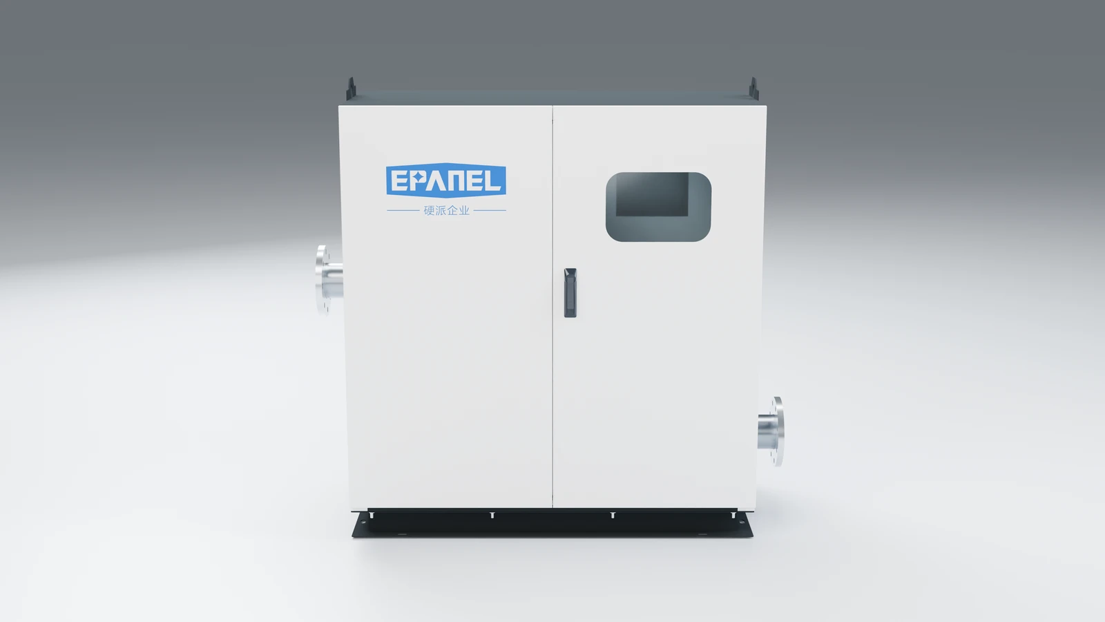
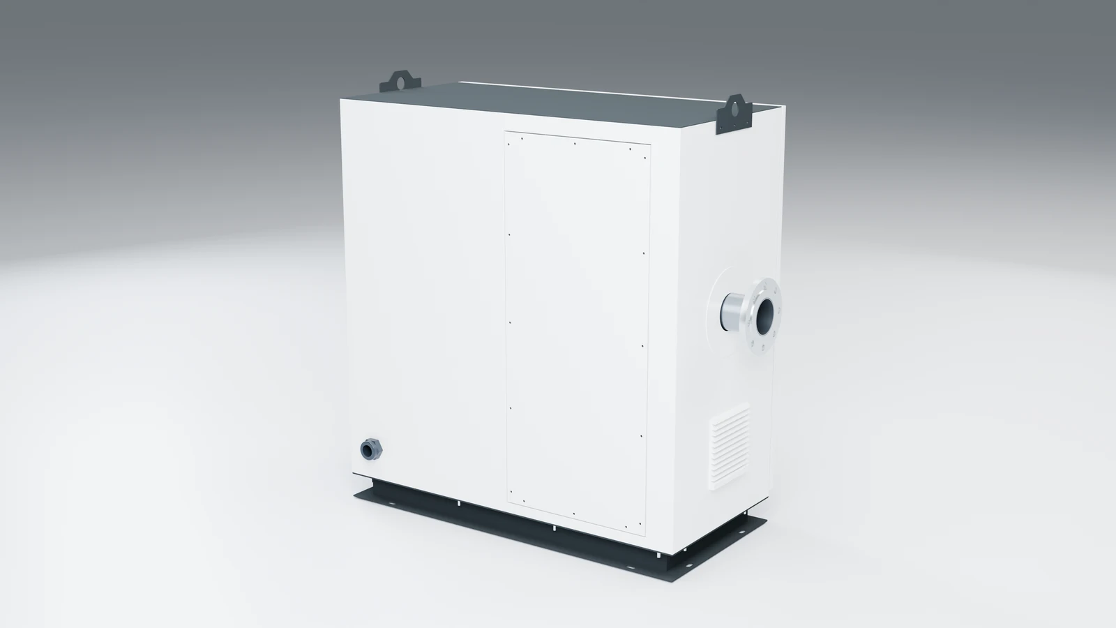
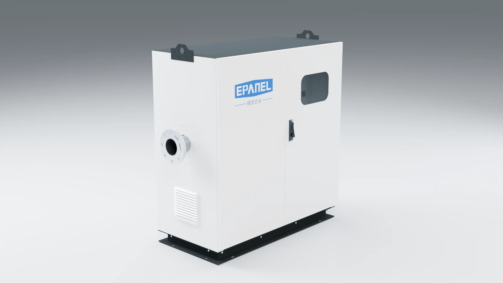
INTERACTIVE PRODUCT VIEW
Drag to rotate, scroll wheel to zoom, or click the cabinet door to open and close.
PROJECT SELECTION
Let each configuration,
All have clear project basis.
TALK TO EPANEL
Contact the hard guys to communicate about water supply conditions, equipment layout and control requirements.
MORE PRODUCTS