Back
Clean the basket in time
Lift out the basket, drain the water, dump the residue, clean the clogged holes and reset them. Do not remove the basket to continue draining, nor flush the residue back into the grease trap.


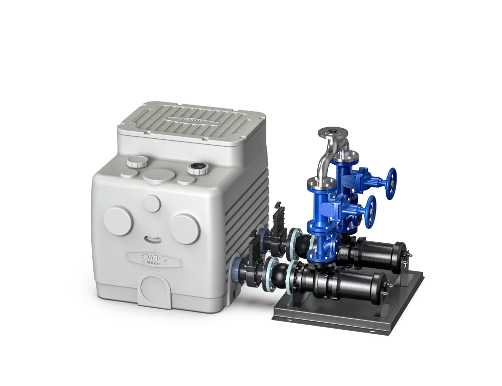
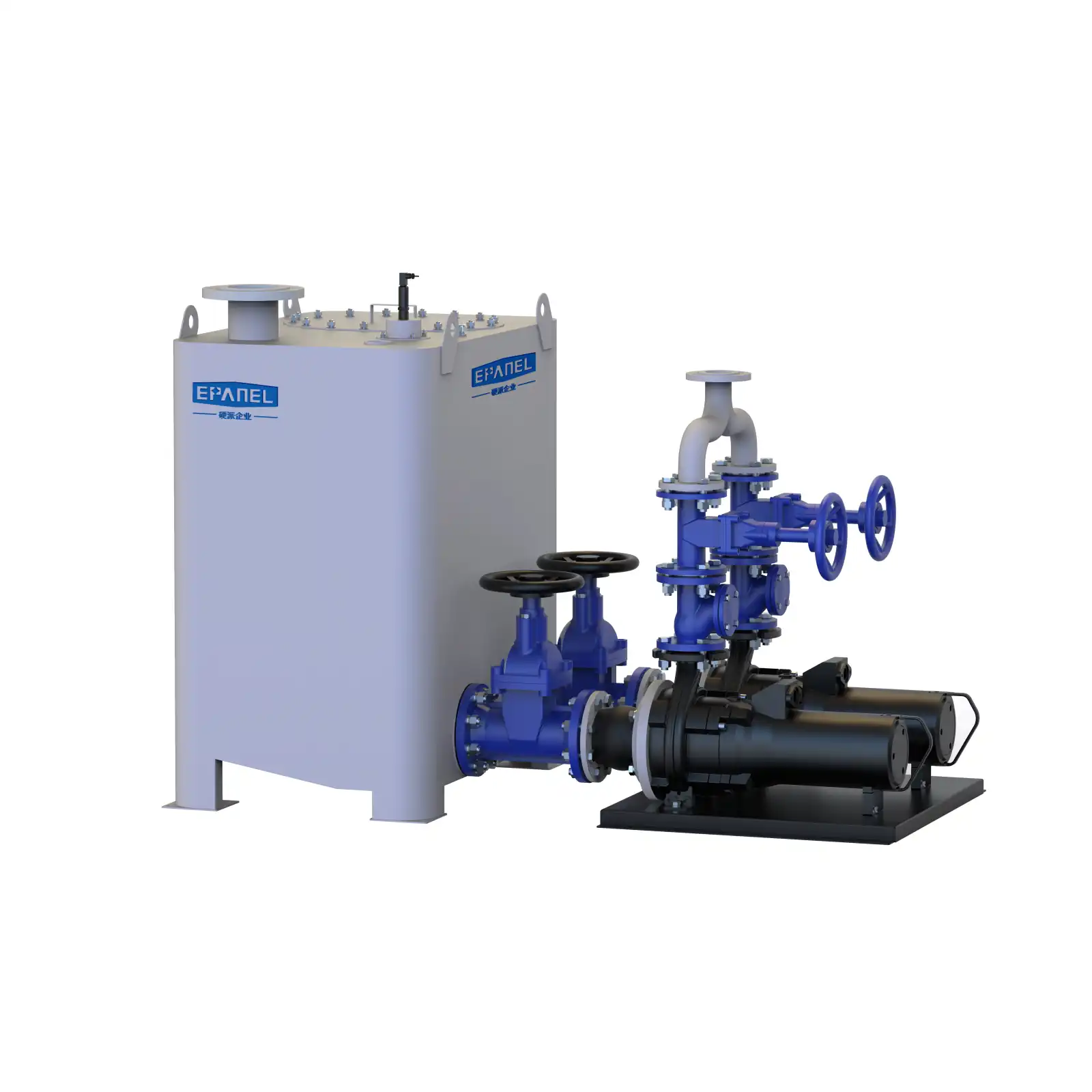
EPANEL / GREASE SEPARATION
Slag separation, separation and promotion,
Centrally arranged below the ground.
Oily wastewater treatment for restaurants, hotels and canteens. The front-end basket catches slag, and the grease in the tank floats and collects. The separated sewage is lifted and discharged by the water pump.
The ground inspection port can be opened to facilitate slag cleaning, oil scooping and water pump maintenance.
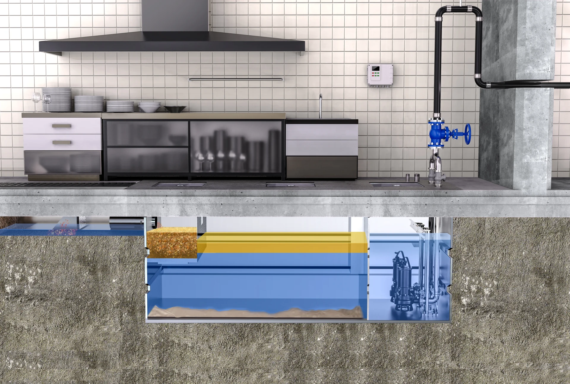
Lift, dump and clean regularly
Oil slicks are manually scooped into collection buckets
Pay attention to the liquid level and pump operating status
01 / HOW IT WORKS
First intercept the residue and then separate the floating oil.
Finally, the separated sewage is lifted and discharged.
The catering wastewater first passes through the basket grille, larger residues and debris remain in the basket, and the wastewater continues to enter the rear section.
Maintenance focus Clean the slag promptly and reset the basket correctly after cleaning.
Taking advantage of the fact that the density of grease is usually smaller than that of water, the separated grease gradually floats up and accumulates on the water surface of the second part of the oil-water separation box.
Maintenance focus Manually scoop out the oil regularly and collect it in a special grease collection bucket.
The separated sewage flows into the lifting area, and the water pump lifts the drainage according to the supporting control and debugging settings, and connects to the subsequent drainage system.
Maintenance focus Check whether the liquid level, pump inlet and drainage are normal.
02 / INSTALLATION & ACCESS
Provide water connection, ventilation and maintenance space,
Included in the installation plan.
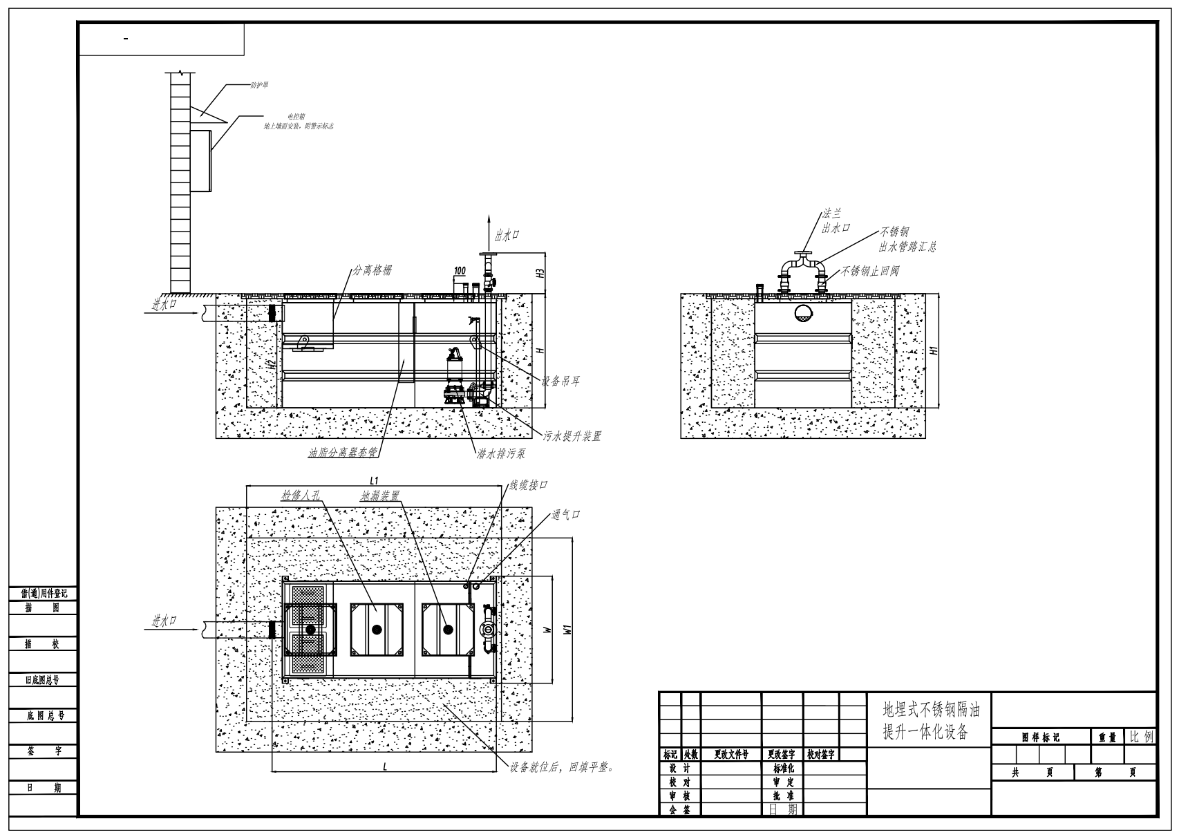
The size, burial depth, foundation, anti-floating, backfill and cover bearing capacity shall be carried out according to the project confirmation drawings and civil engineering design. The schematic diagram does not serve as a basis for construction to scale.
03 / ROUTINE MAINTENANCE
Arrange special personnel for frequent inspections,
Slag cleaning, oil scooping and water pump inspections are continuously implemented.
Lift out the basket, drain the water, dump the residue, clean the clogged holes and reset them. Do not remove the basket to continue draining, nor flush the residue back into the grease trap.
Use a long-handled tool to slowly scoop up the floating oil, put it into a grease collection bucket, cover it and transport it away. Avoid vigorous stirring, and the caked grease should be collected in batches.
Observe the liquid level, drainage capacity and operating sound. The lifting area, pump inlet and liquid level components should be inspected regularly by maintenance personnel, and foreign matter and attached oil should be dealt with in a timely manner.
It is recommended to clean the slag every day, and arrange oil scooping every day in the initial stage, and adjust it according to the drainage volume, slag content and oil accumulation speed; increase the number of inspections during peak periods. Exceptions should be handled immediately if found.
Remove residue before washing dishes. Rags, wet wipes, cleaning balls, plastic bags, tableware, metal parts, large bones and other hard objects should be collected separately, and source interception and basket maintenance should be implemented at the same time.
First limit or suspend the relevant water inflow, and contact maintenance personnel to investigate. Before inspection and cleaning, stop the machine and cut off and isolate the power supply to prevent automatic starting of the pump; repeated forced starts or repeated resets are not allowed.
Water pump extraction, impeller removal and electrical inspection are completed by professionals. It is prohibited to enter the underground box or pit by yourself; daily cleaning of slag and oil scooping should be done from outside the ground maintenance port.
04 / PROJECT CONFIGURATION
Provide drainage requirements and site information,
Communicate equipment selection, interfaces and maintenance conditions.
Equipment parameters and scope of supply shall be subject to the project confirmation plan.