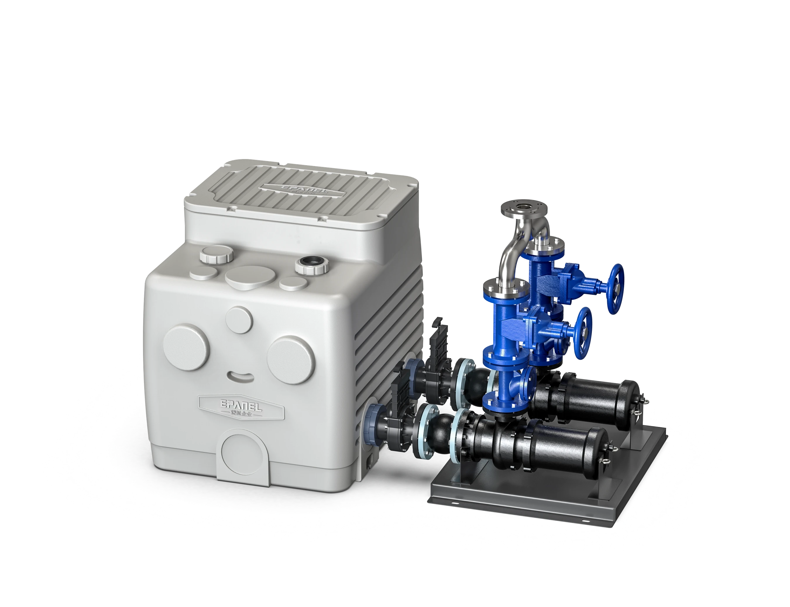
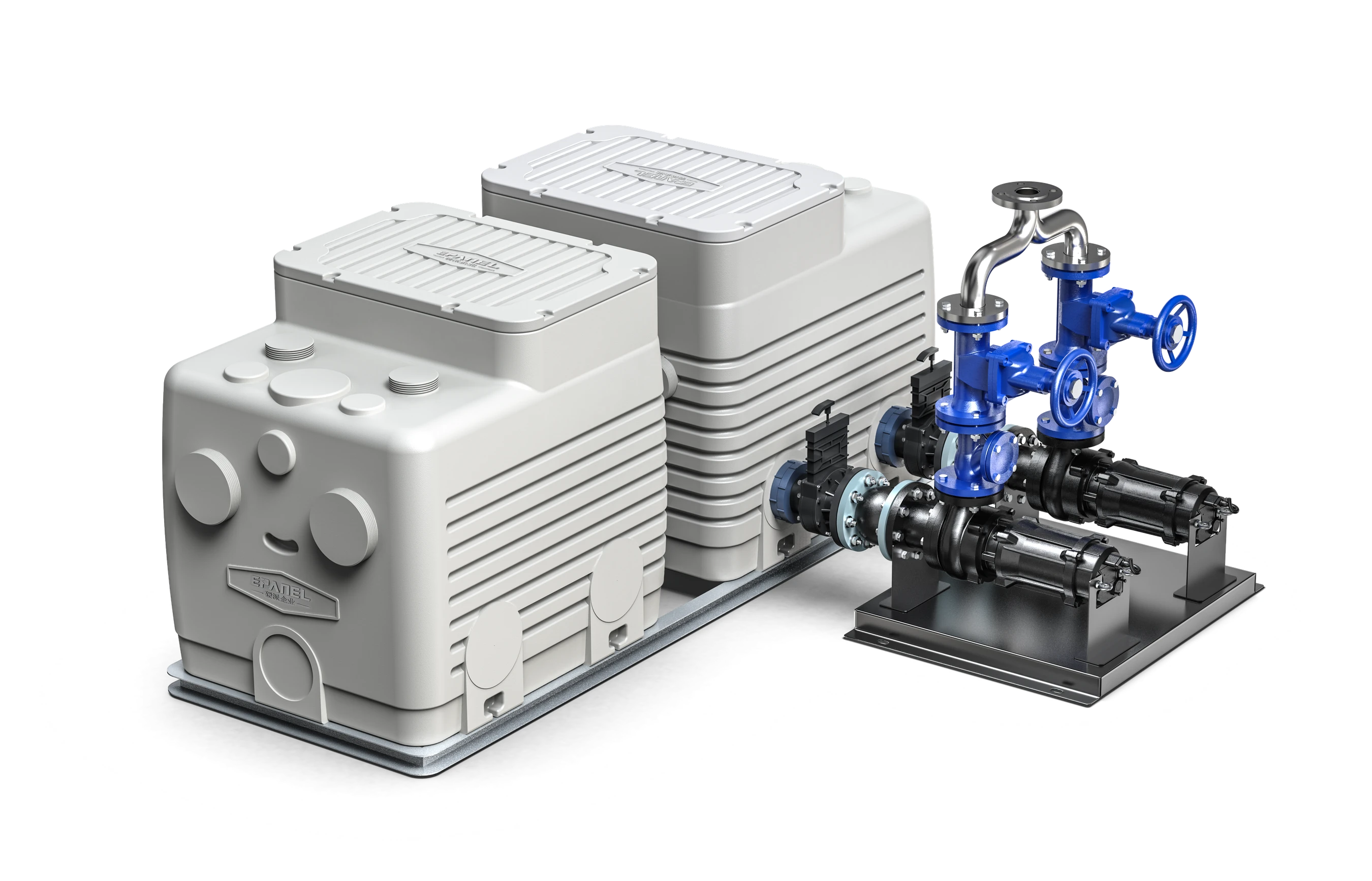
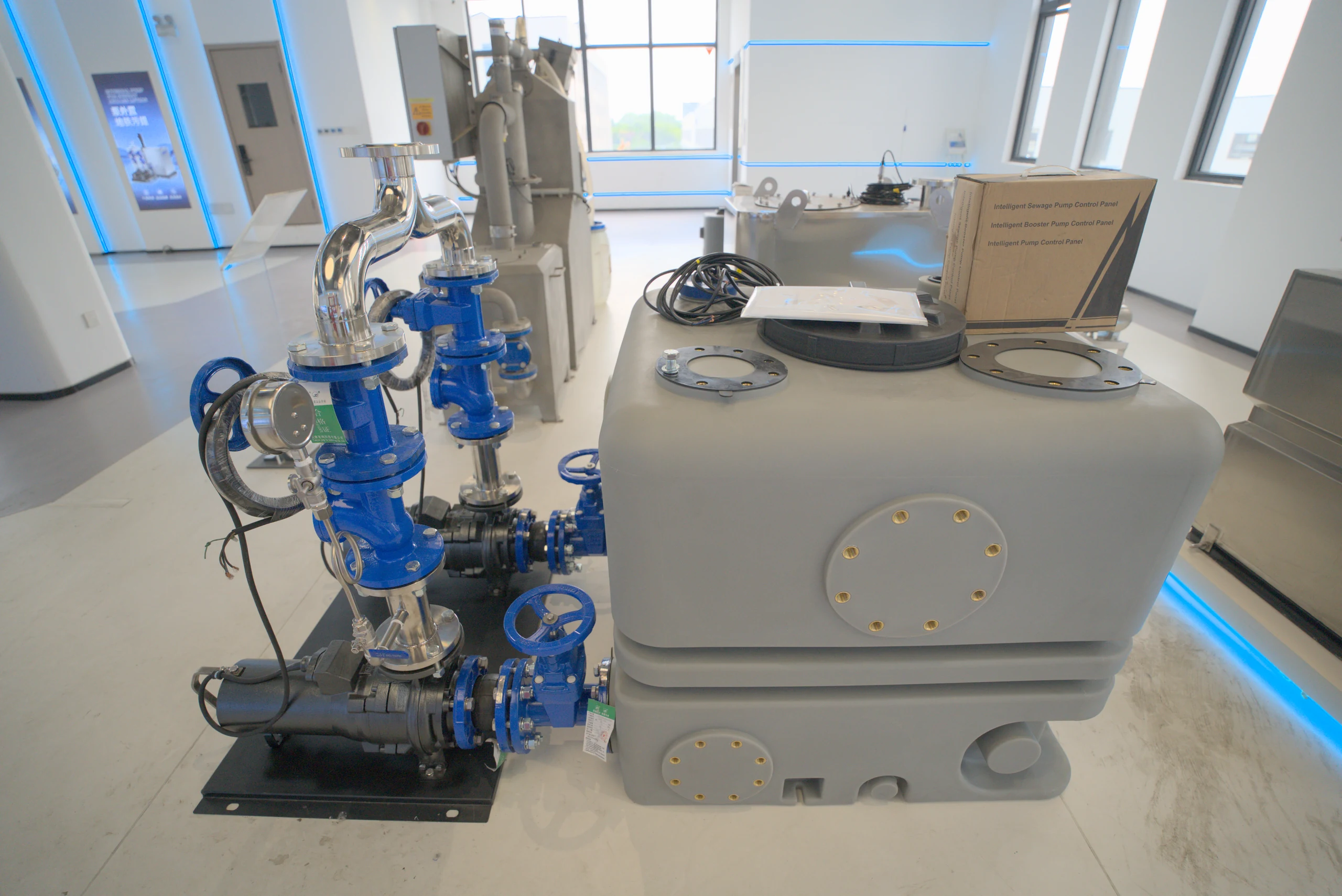
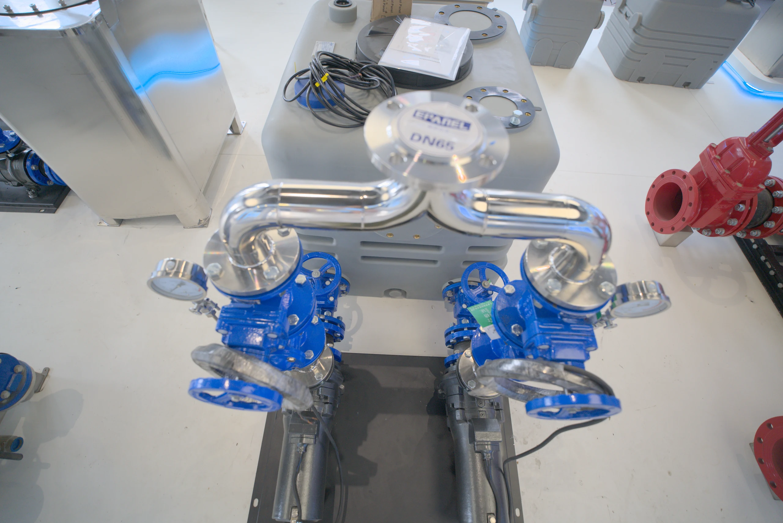
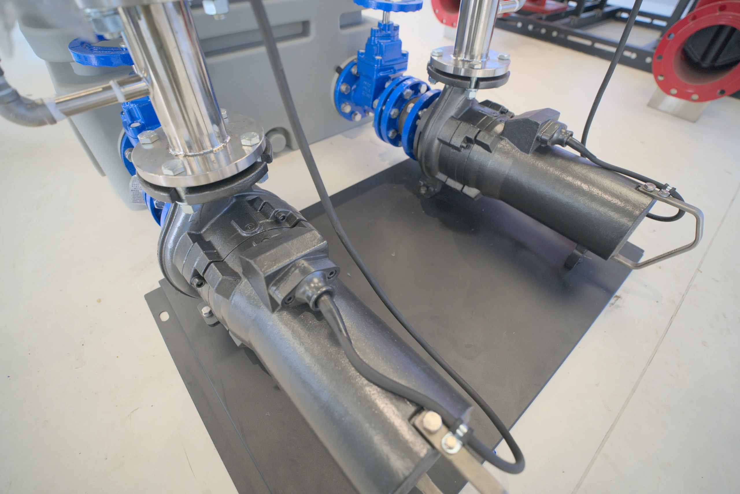
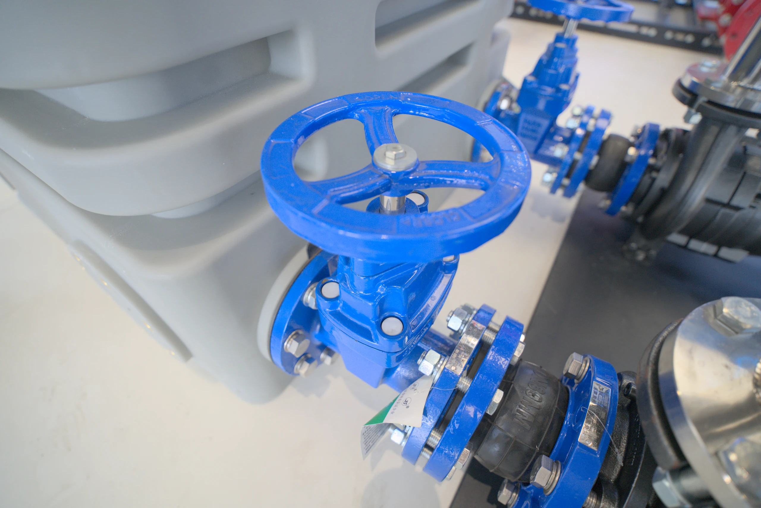
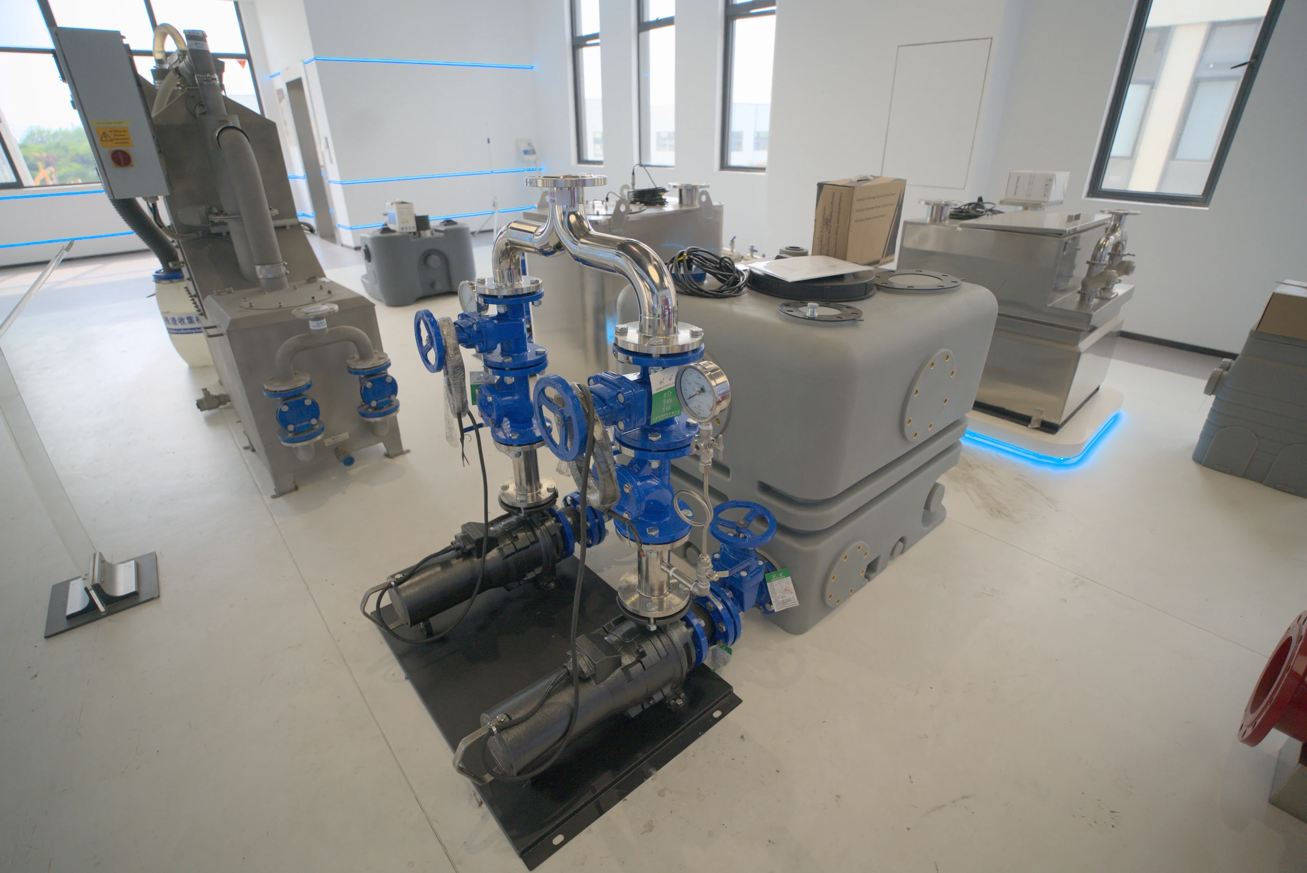
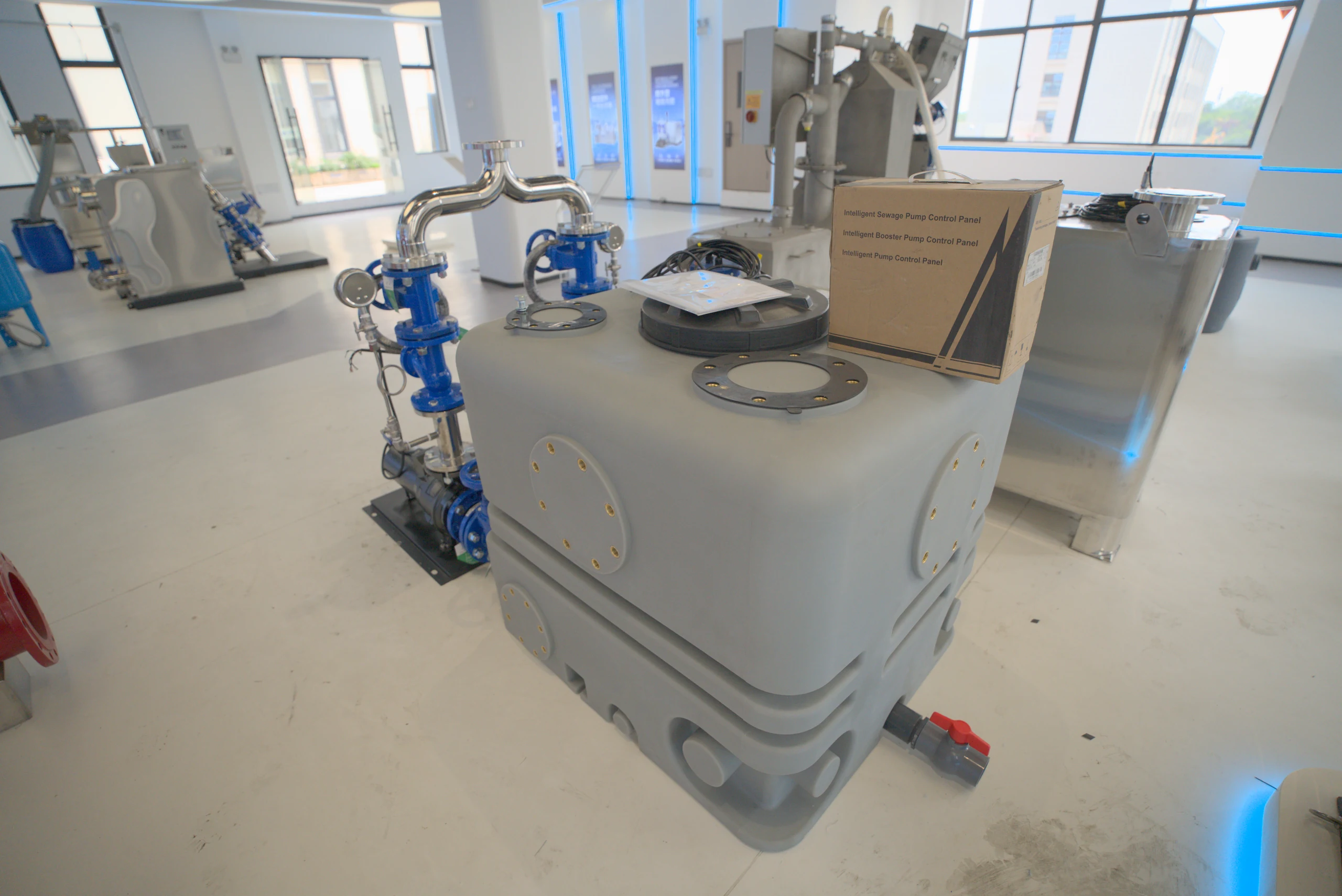
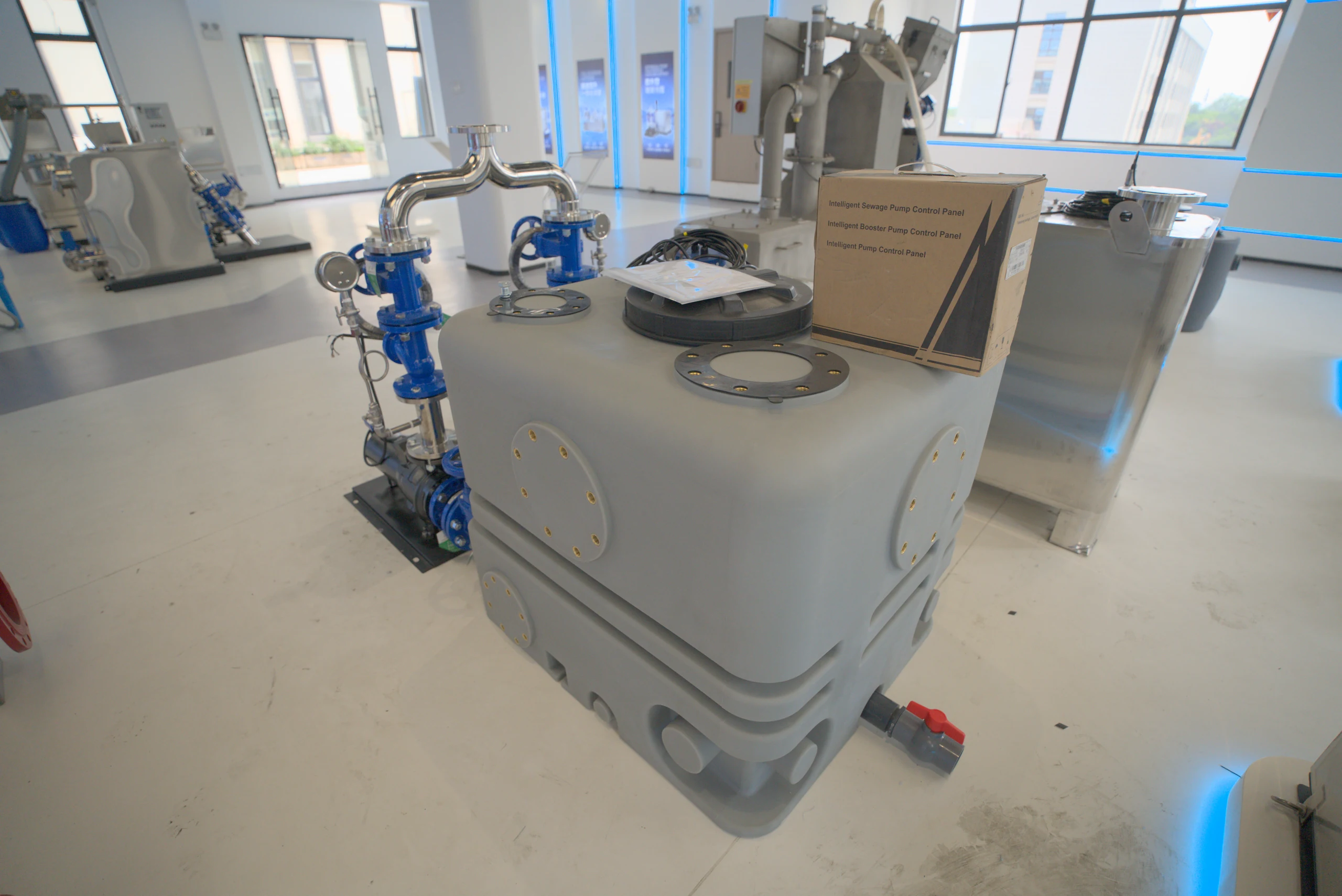
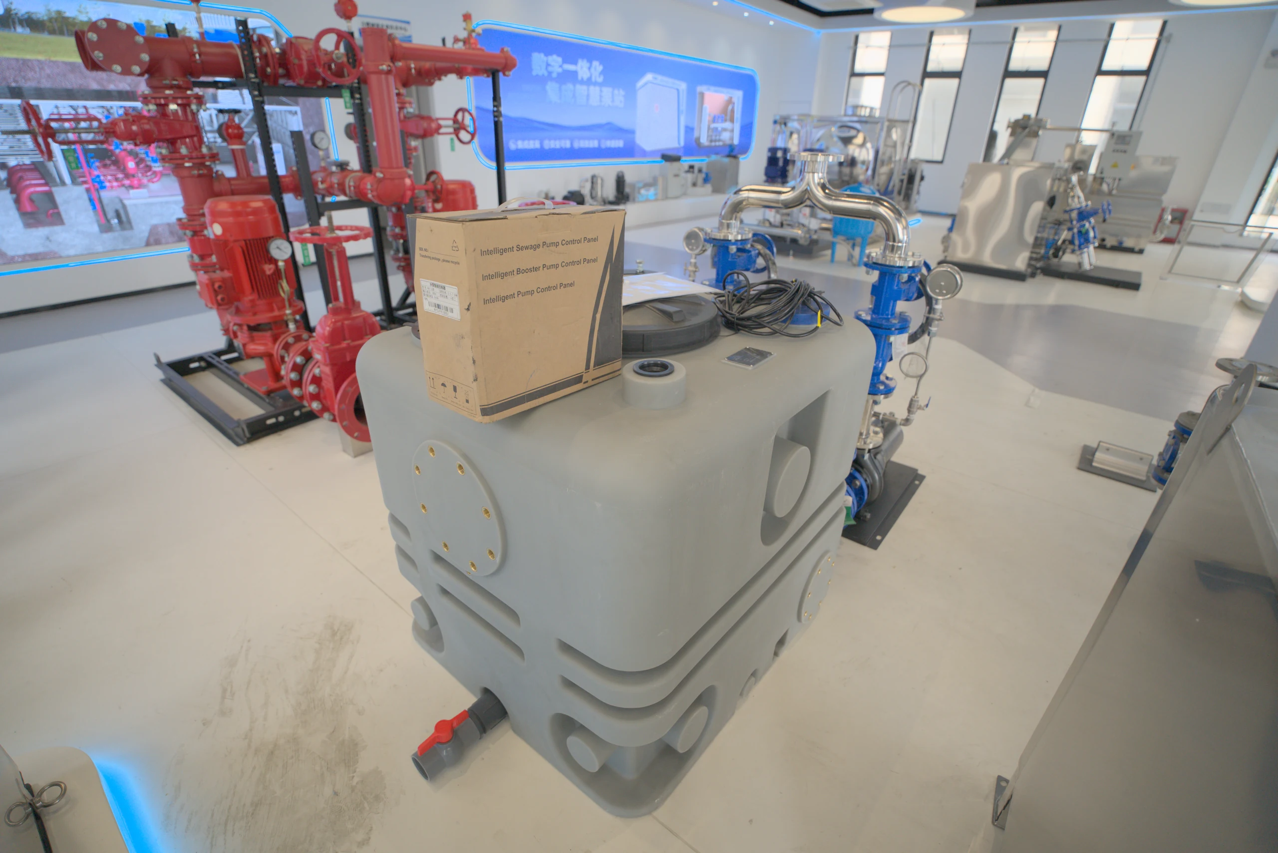
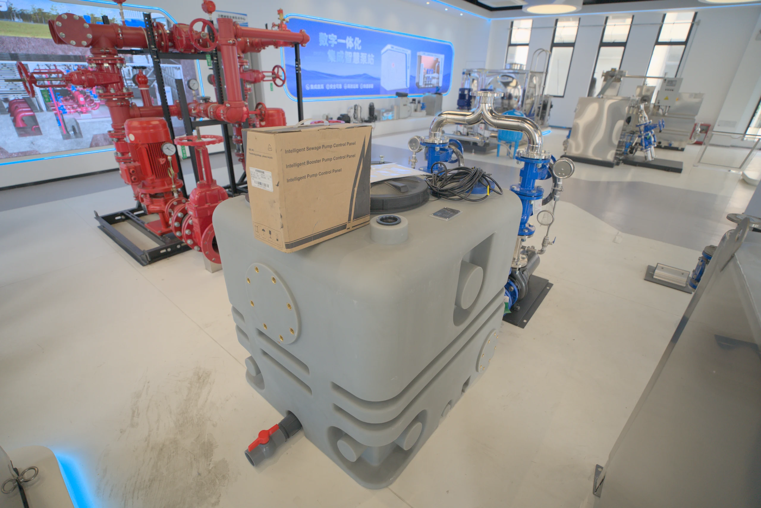
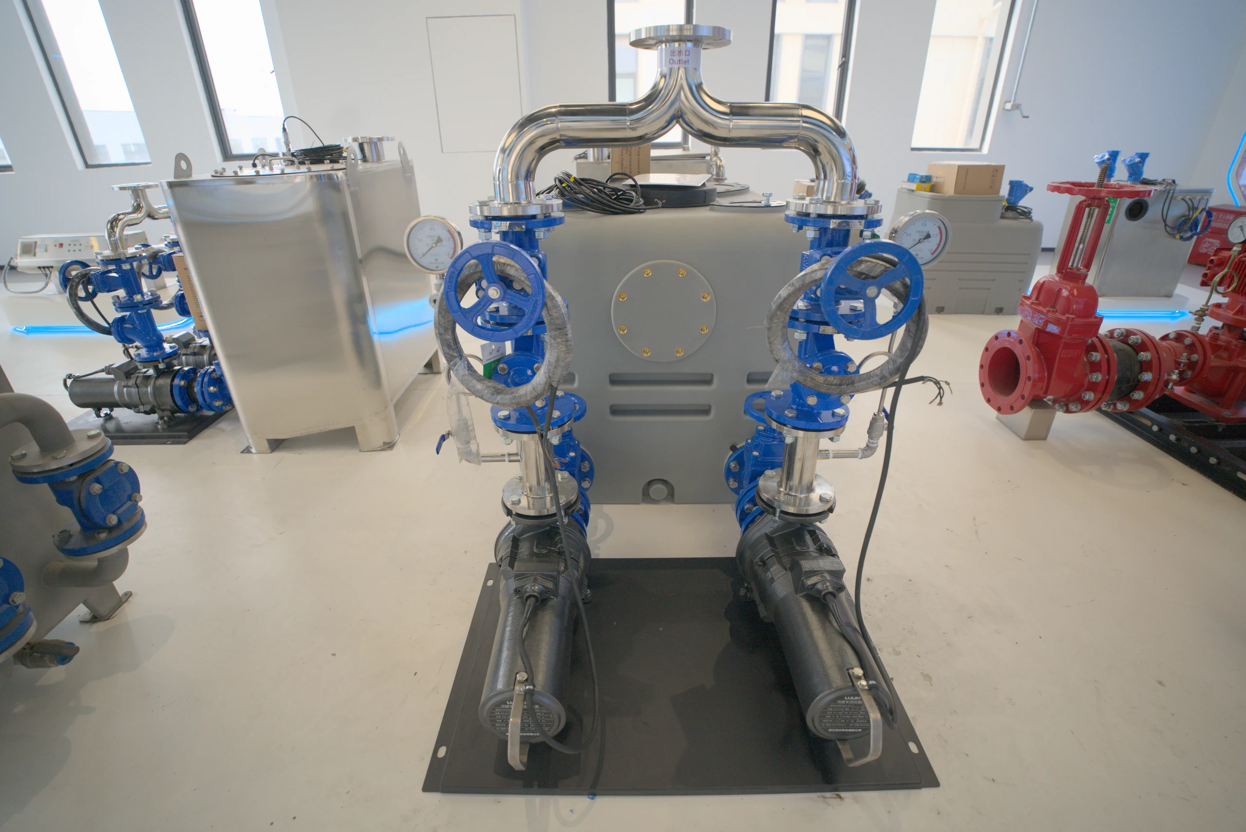
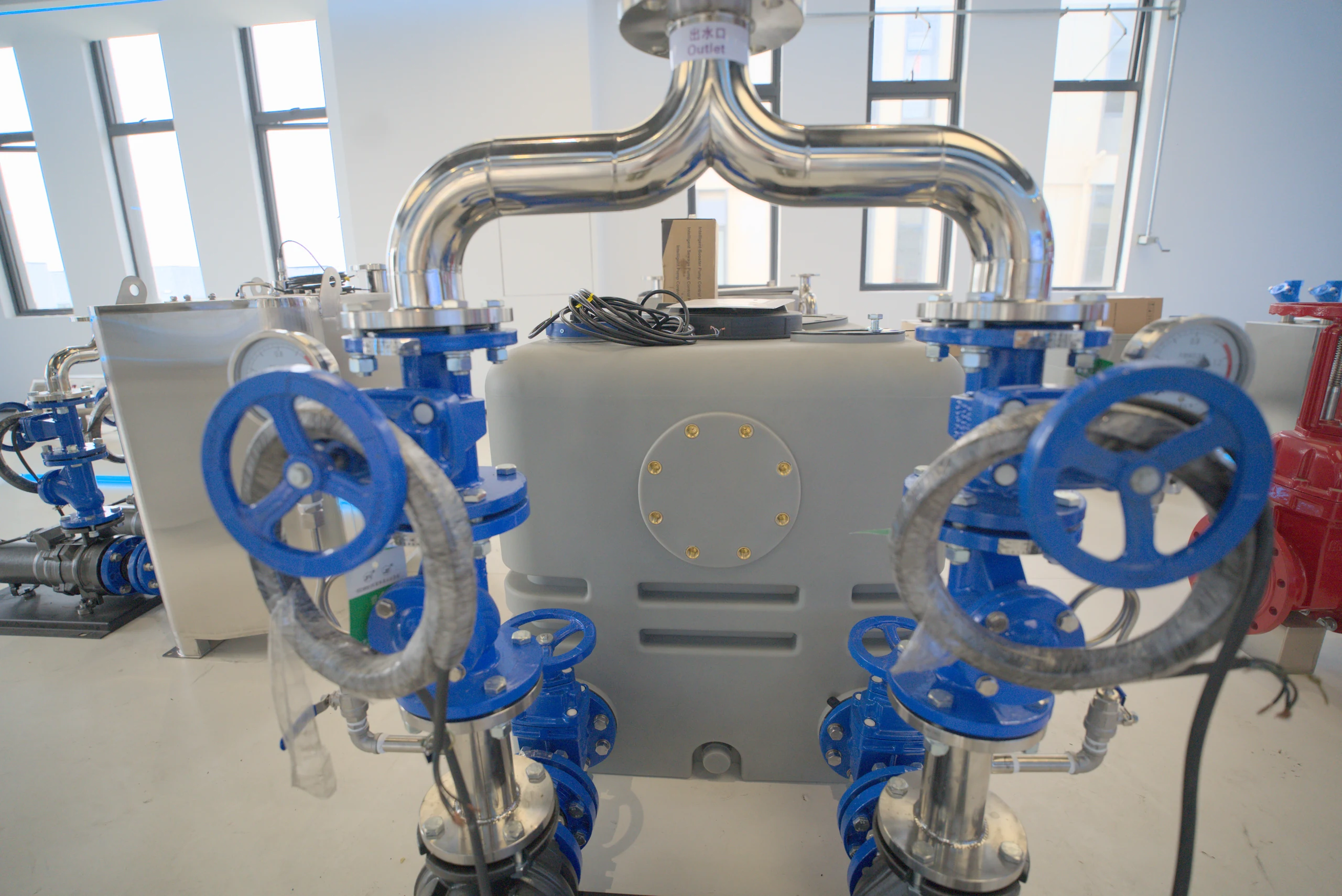
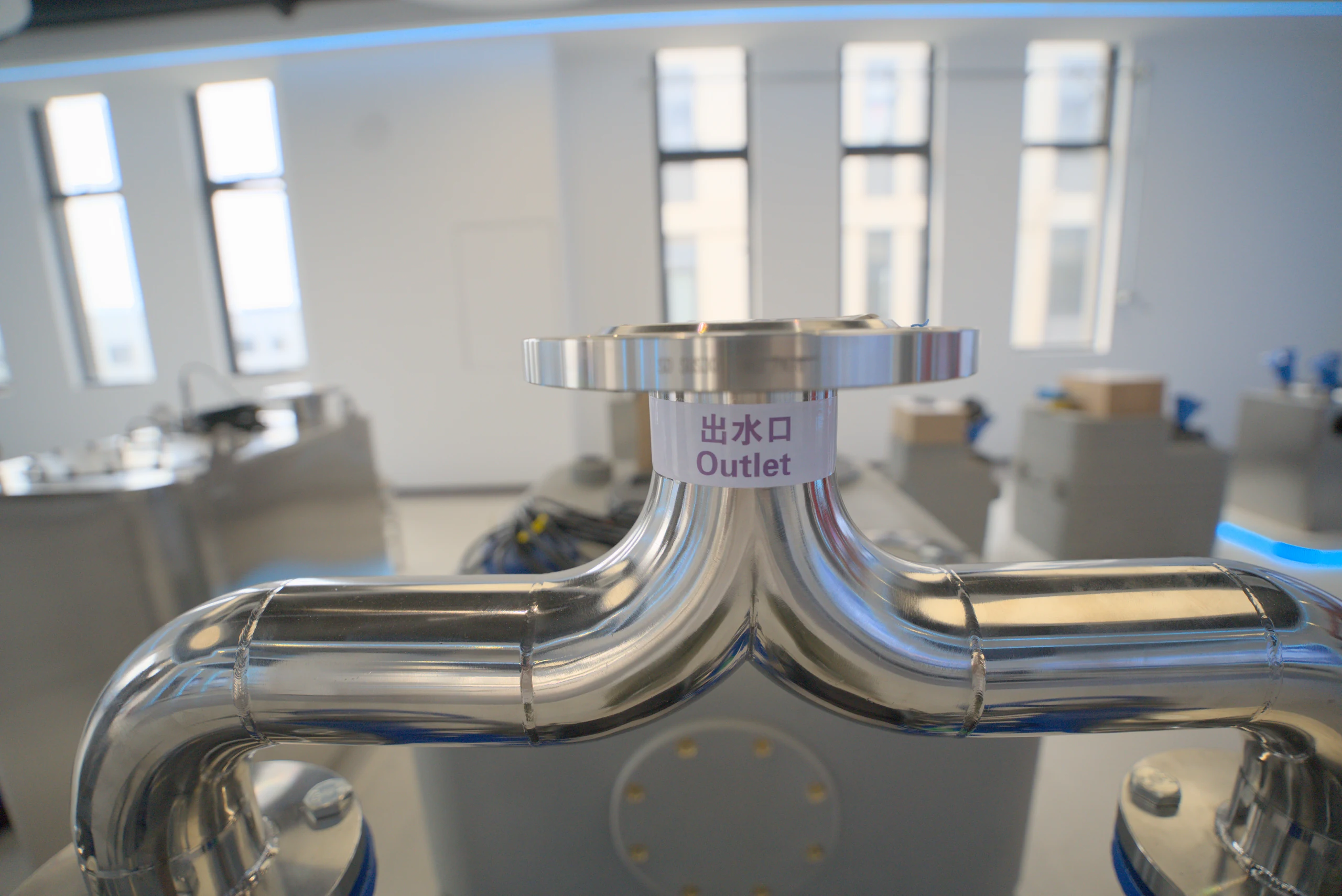
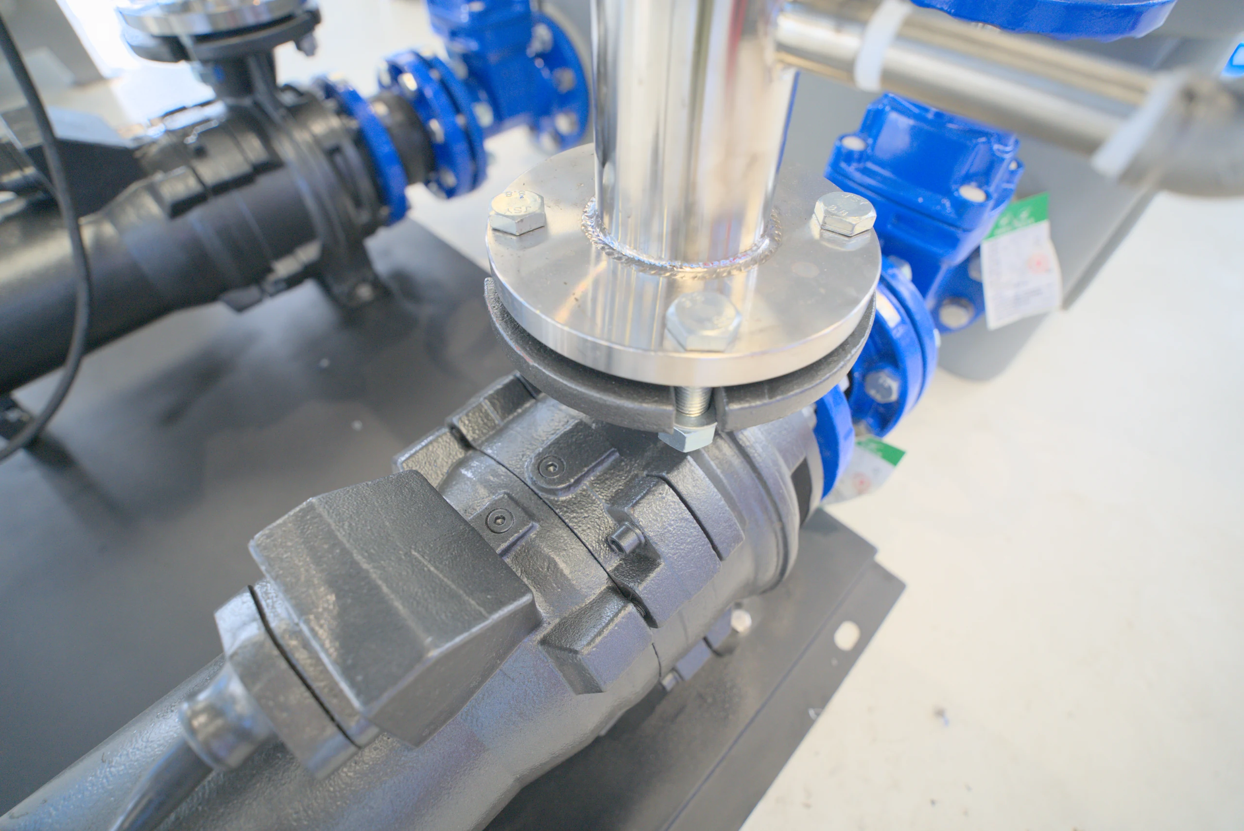
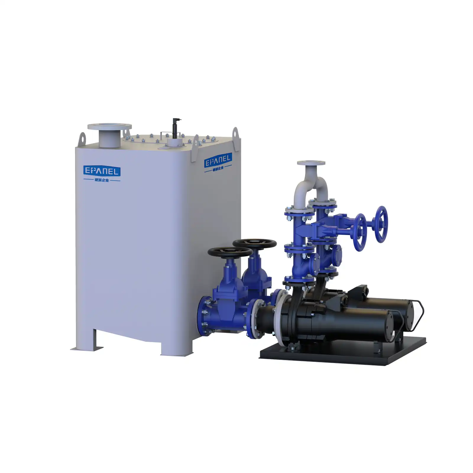
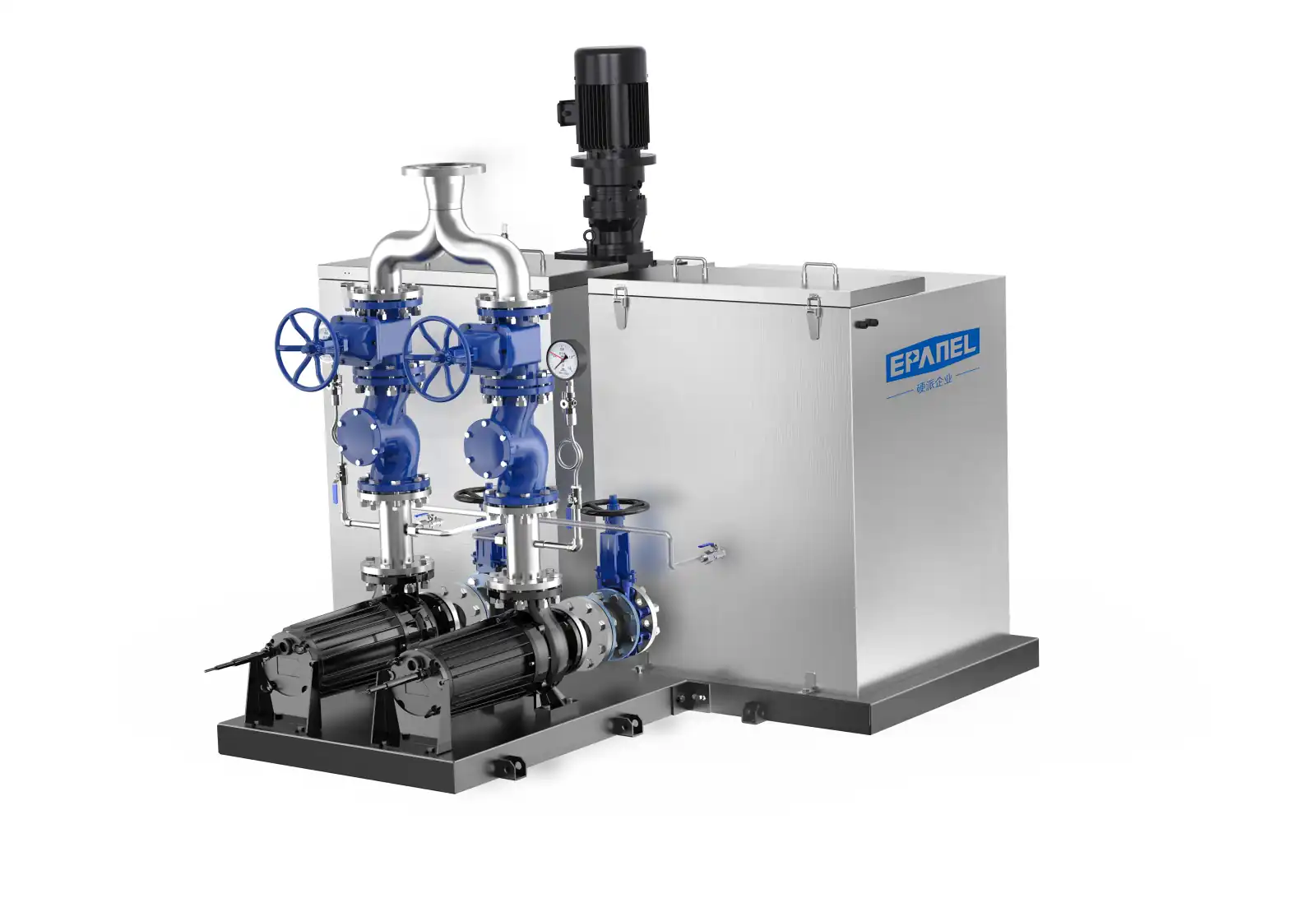
EPANEL / EXTERNAL PUMP SYSTEMPE water collecting box External horizontal pump unit Product renderings
EPANEL · PWT Series / EXTERNAL PUMP
PE pump external sewage lifting station。
External power makes maintenance easier.
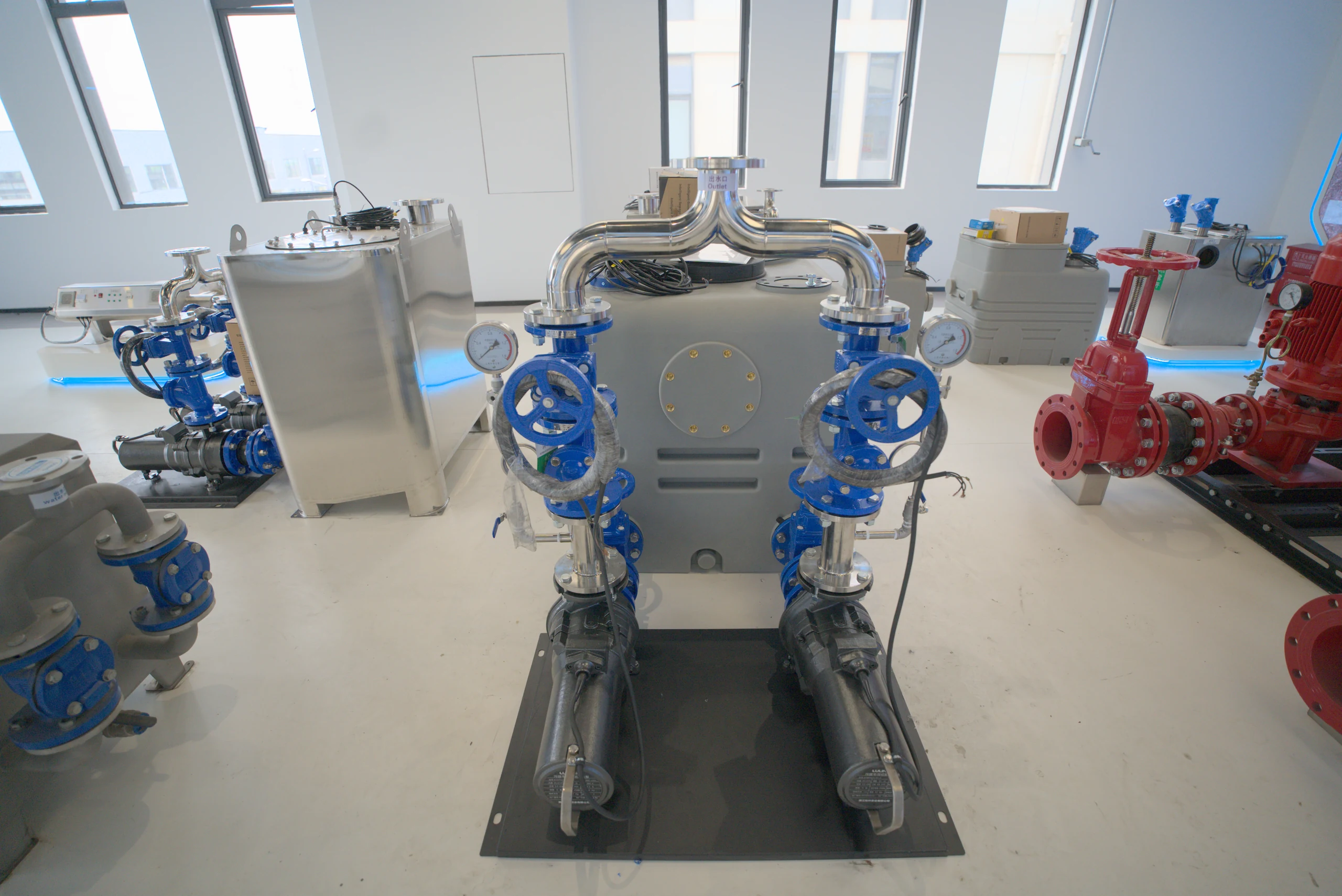
The PE water collection box and external horizontal pump set are arranged in a coordinated manner. From sewage collection to lifting and transportation, every link is clearly visible.
ENGINEERED FOR ACCESS Make maintenance within reach.
Series box volume
250–1000L
250 / 500 / 1000 L
Cabinet material
PE
Water collecting space·Clearly formed
Pump set structure
ExternalHorizontal pump
The pump set is located outside the box
Sample power supply parameters
380V
The specific configuration is confirmed by selection.
01 / DESIGNED AROUND ACCESS
Give the power, Keep it within reach.
Collect water, connect, lift and discharge water. Start with the structure and understand a set of equipment.
PWT / EXTERNAL DUAL PUMP
Click on the blue hotspot to view part descriptions
THE DETAILS THAT MATTER
01 / External horizontal pump
The motivation is outside. maintenance is more relaxed.
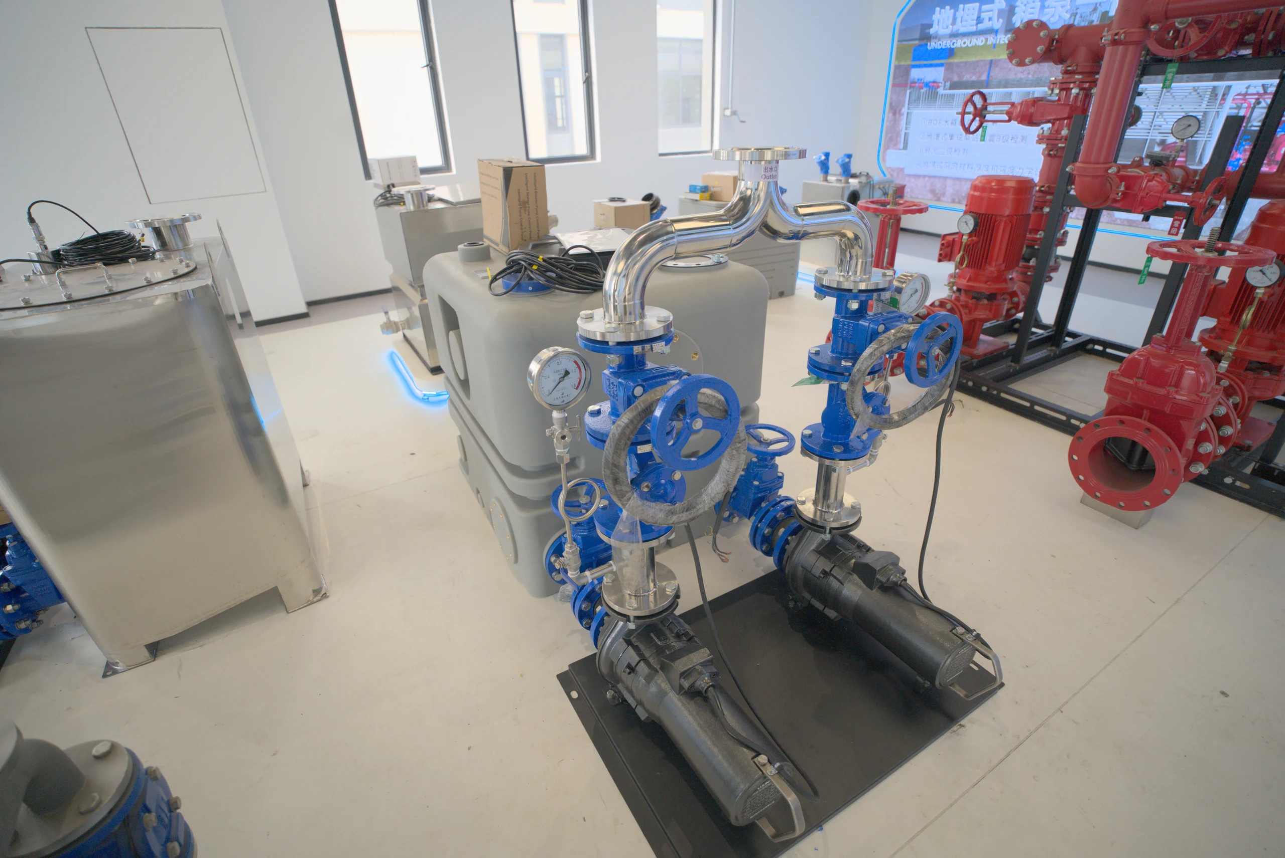
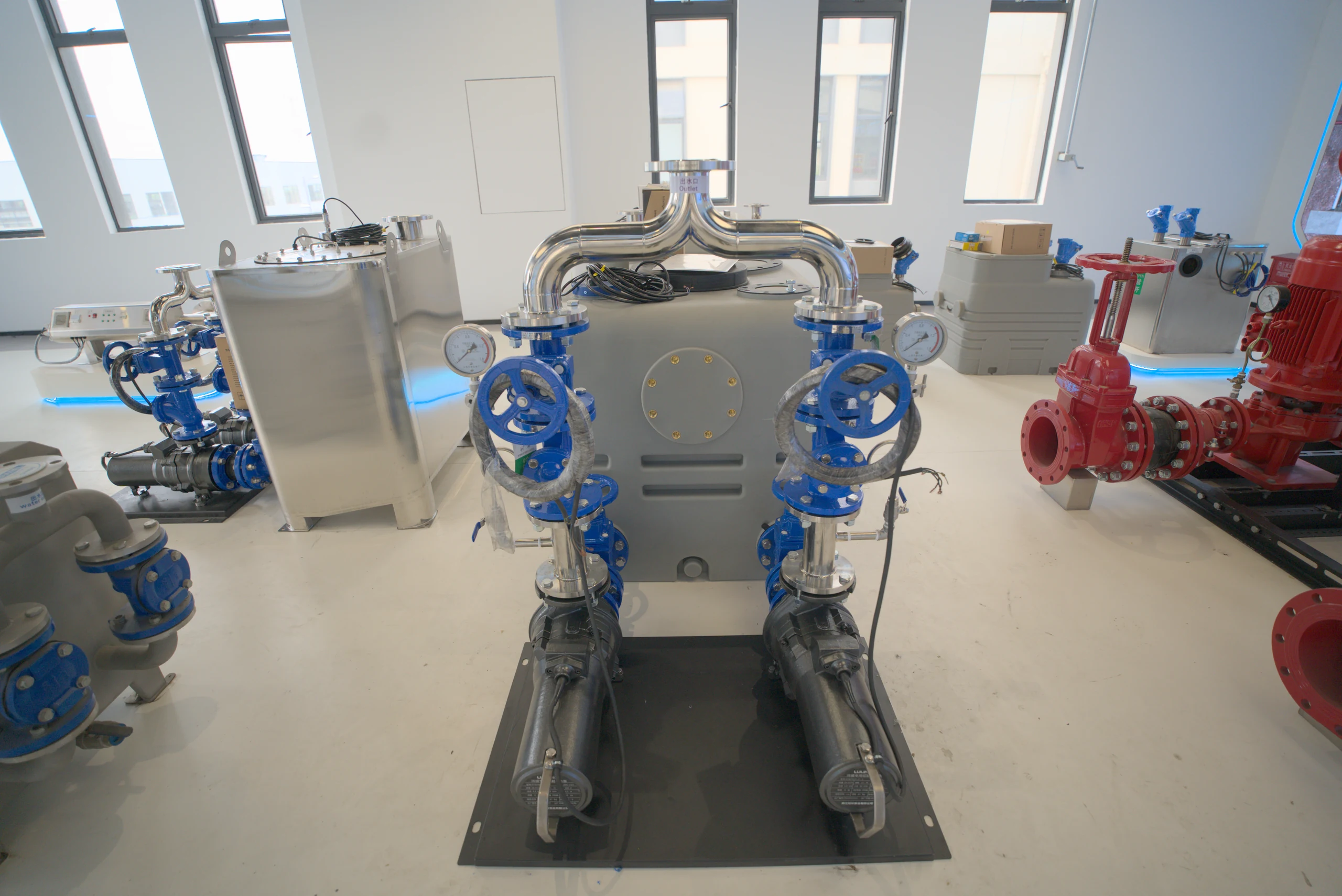
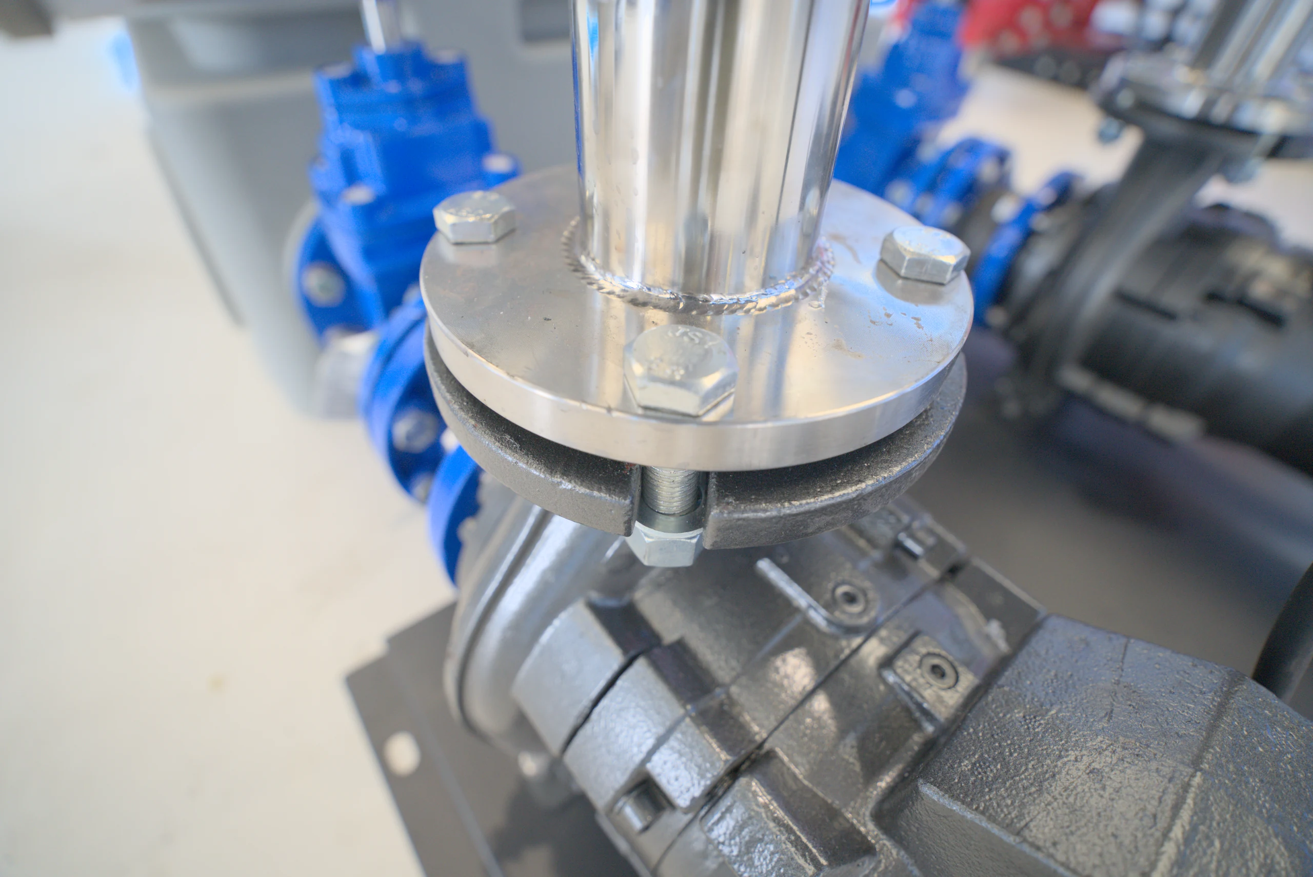
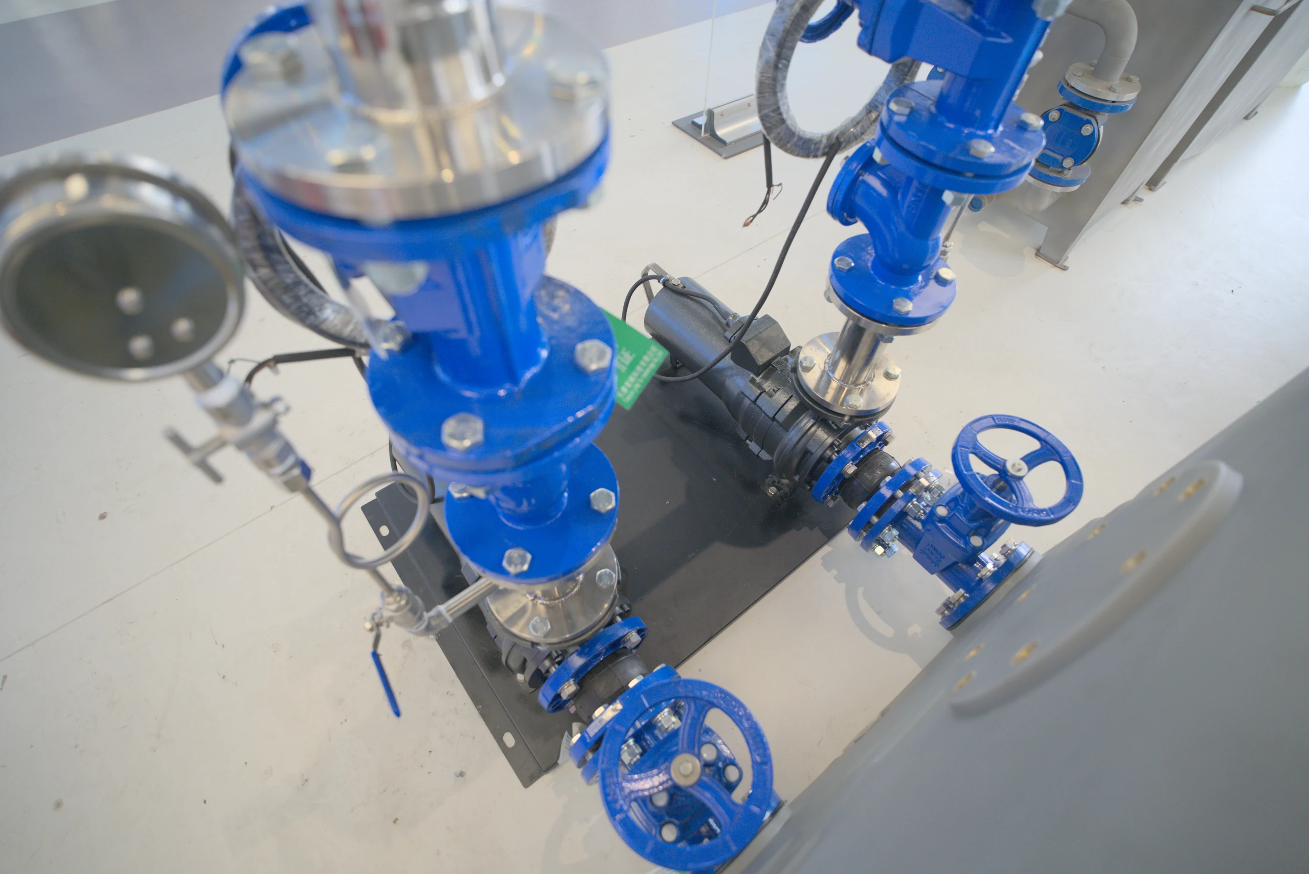
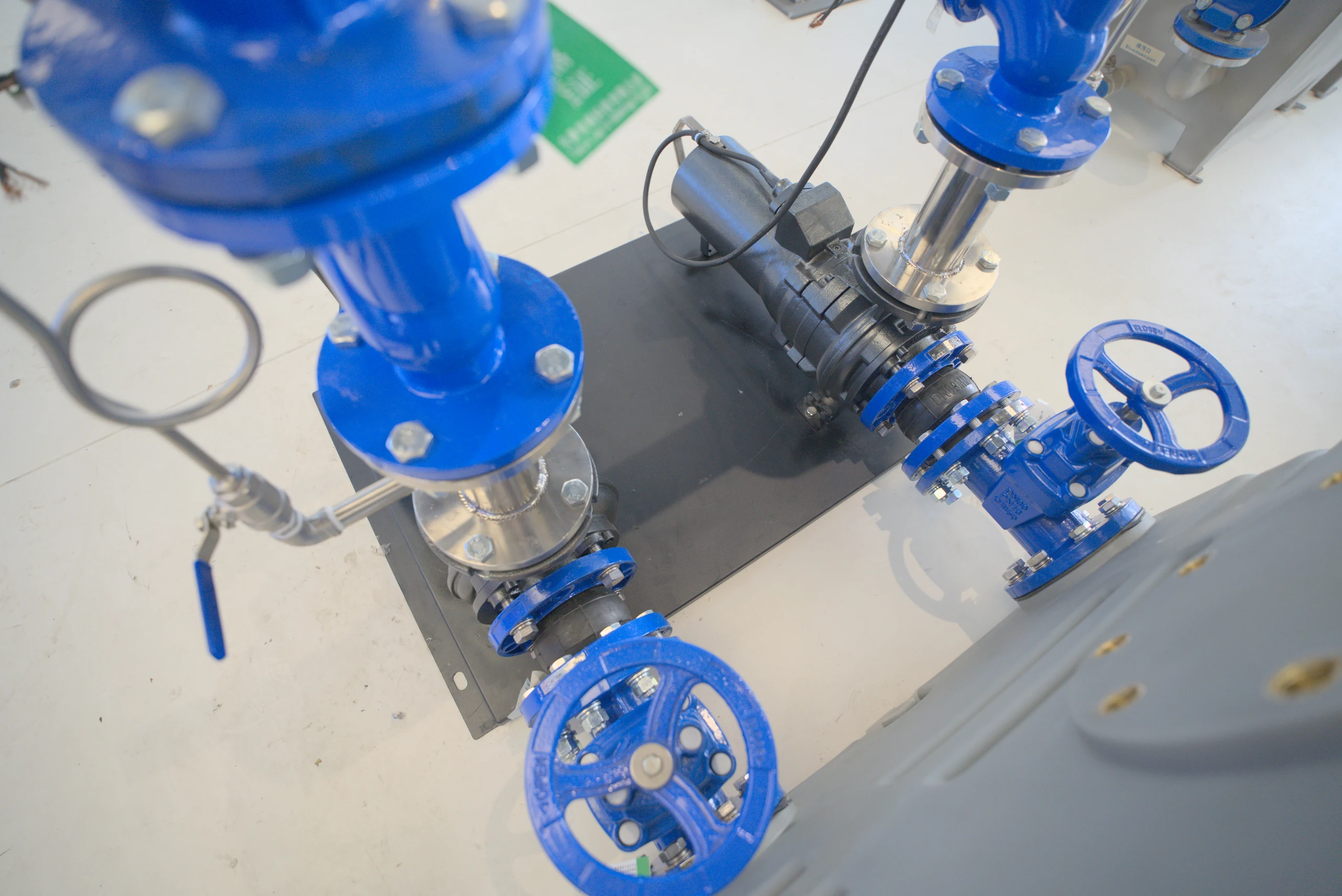
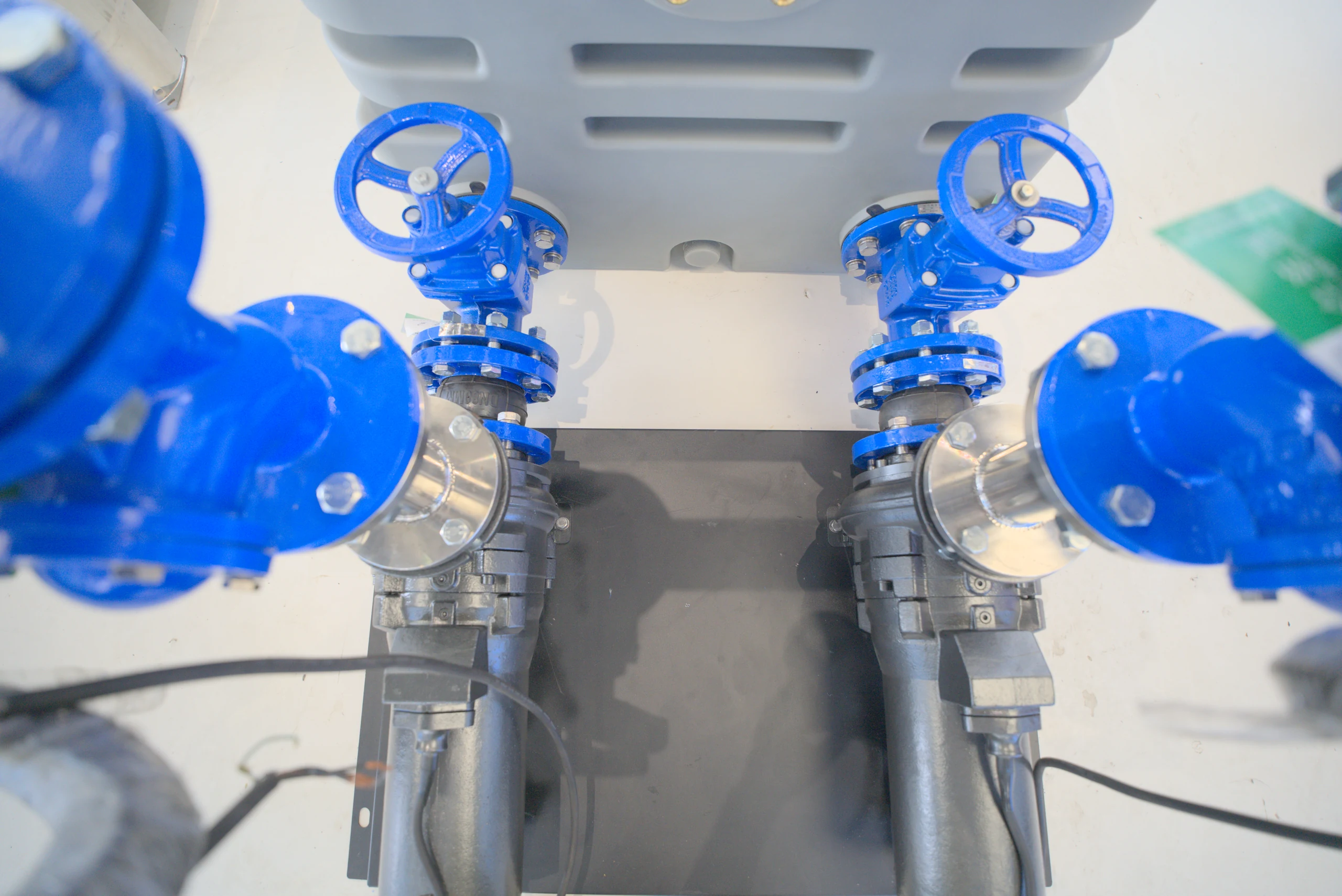
The horizontal sewage pump is arranged outside the PE box, and the pump unit is arranged separately from the water collection space. During inspection, you can directly observe the pump body and connection parts, leaving a clear operating position for pump unit maintenance.
External pump setHorizontal layoutEasy to access
02 / Outlet valve group
Two-way transportation. converges in an orderly manner.
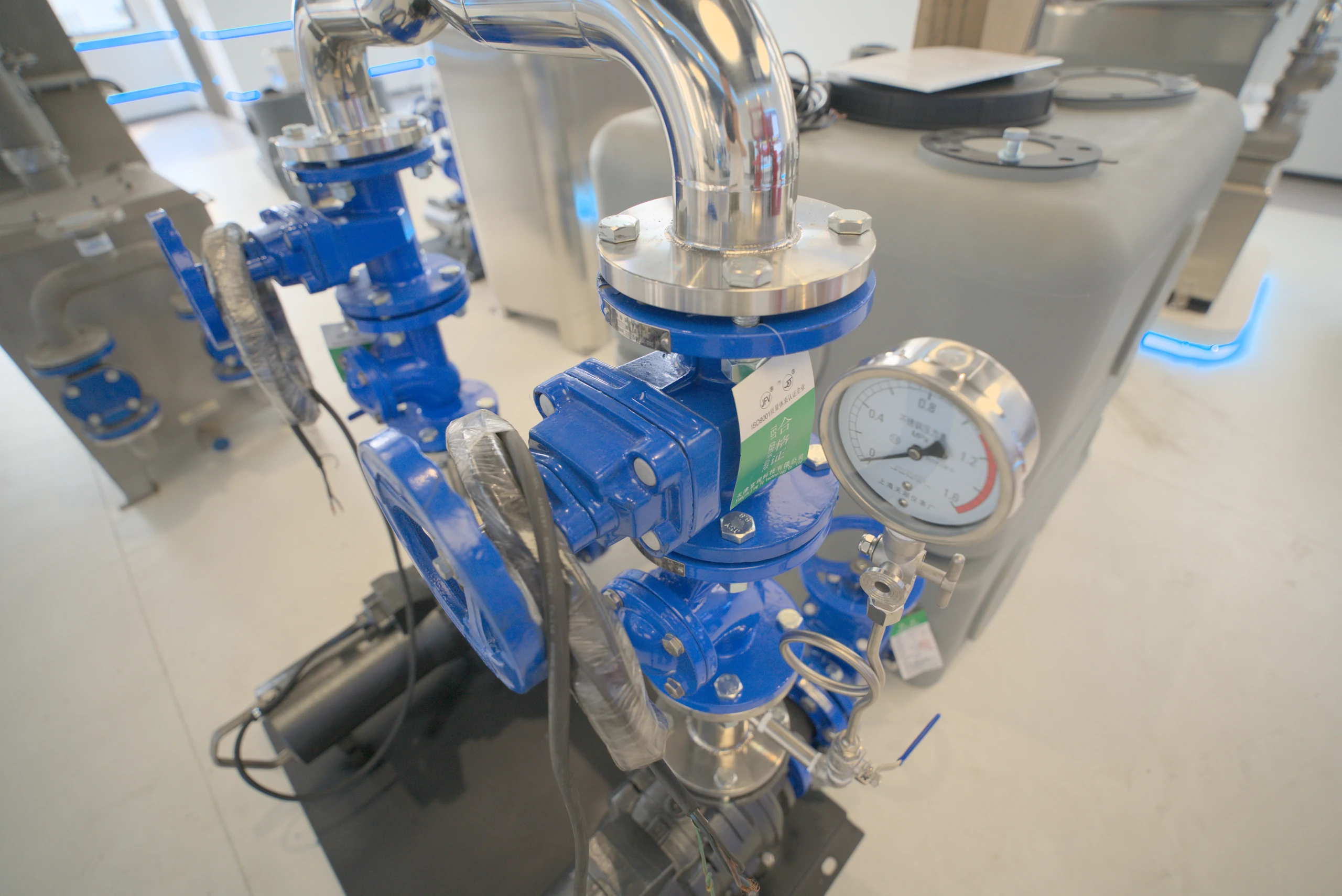
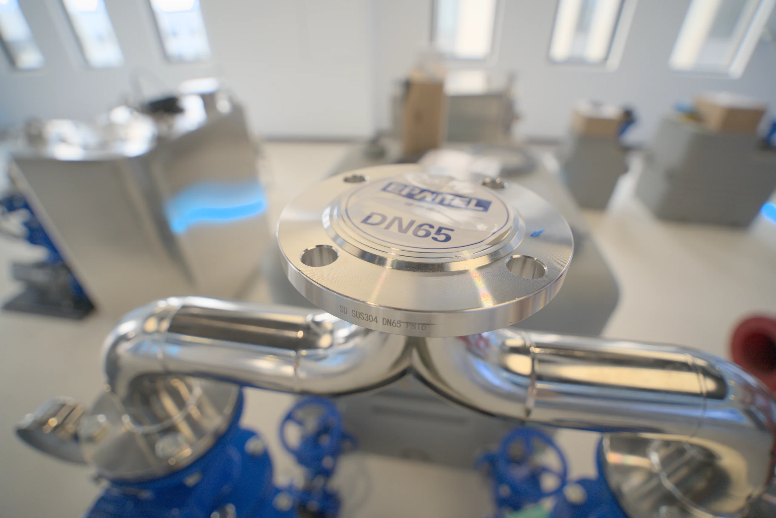
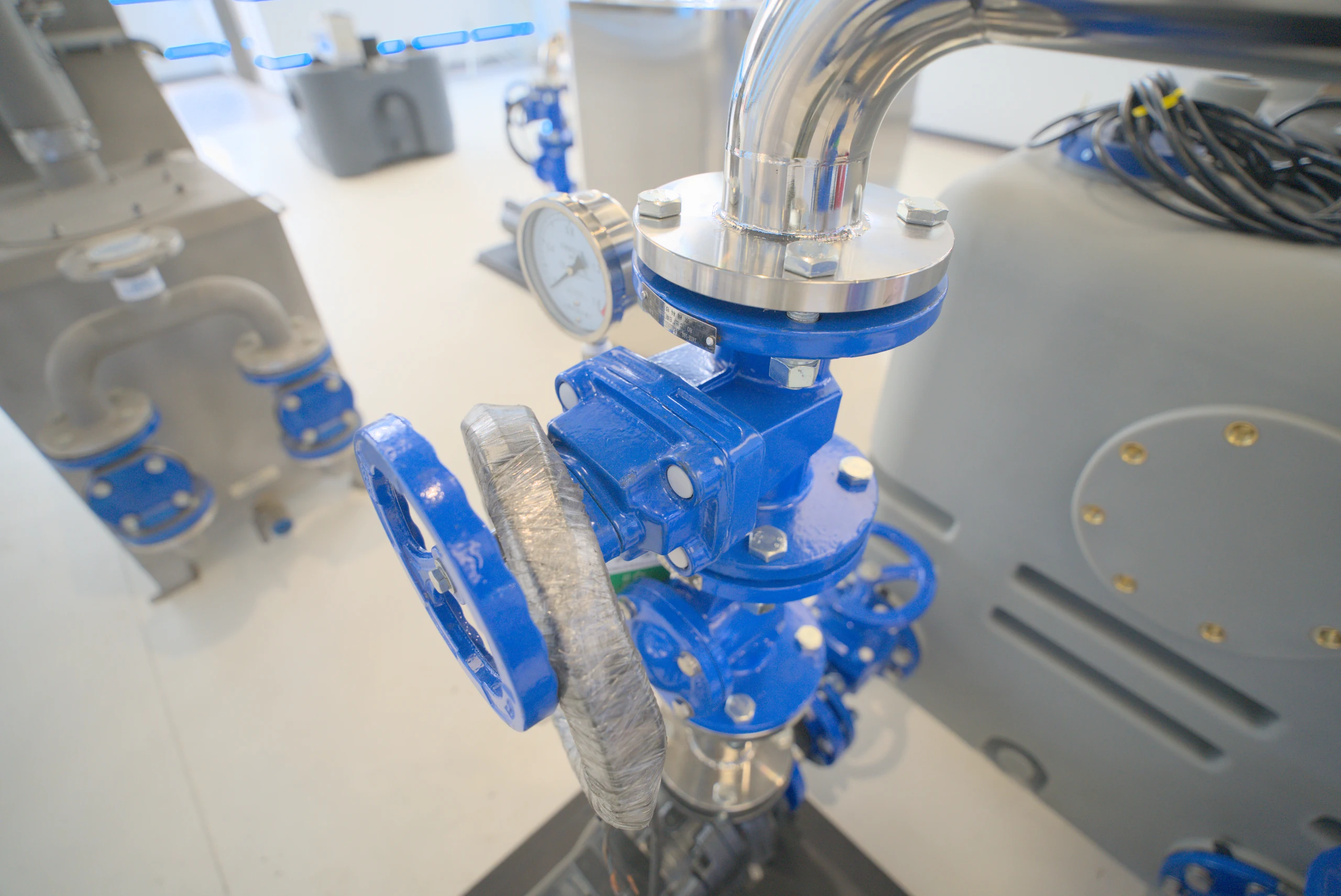
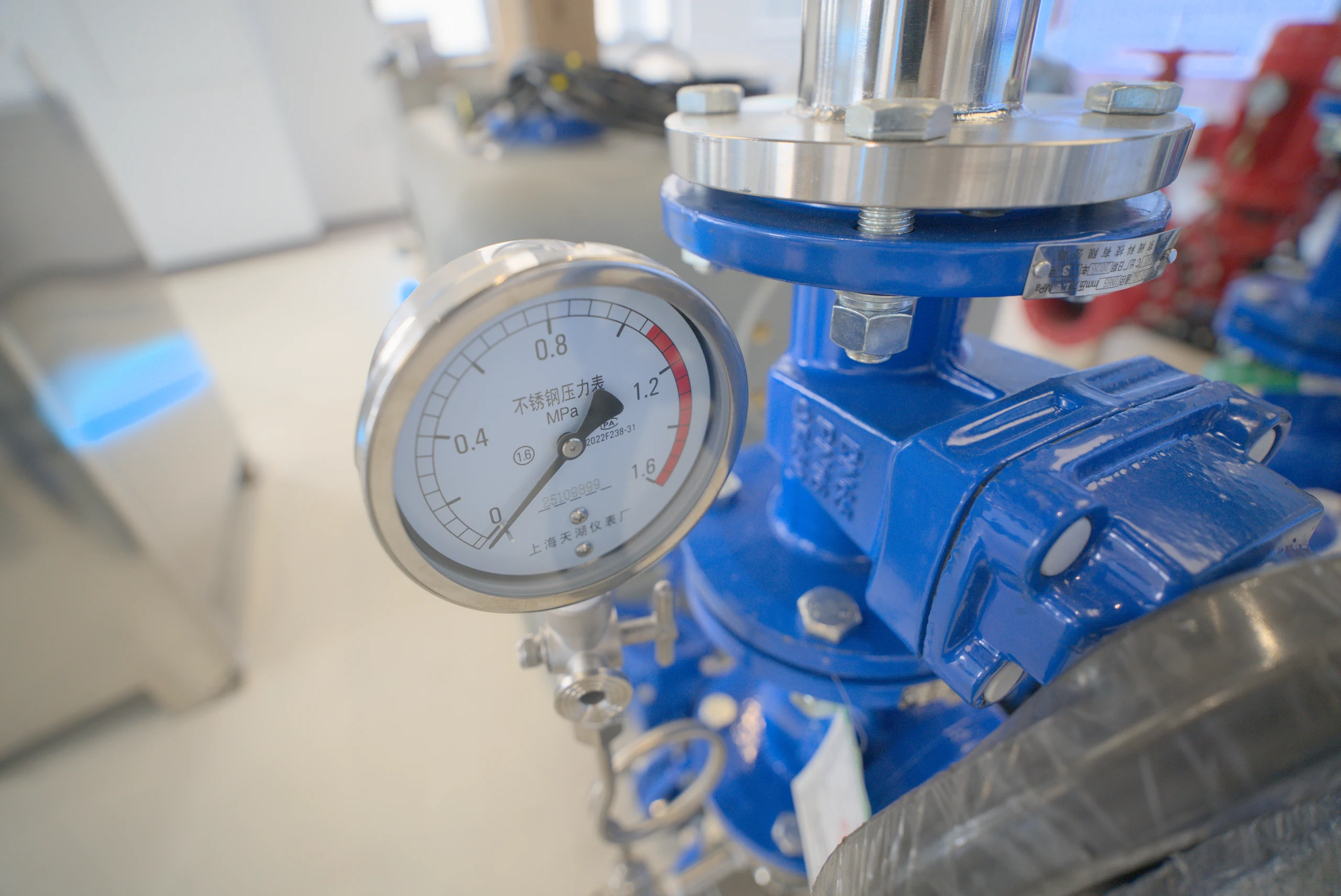
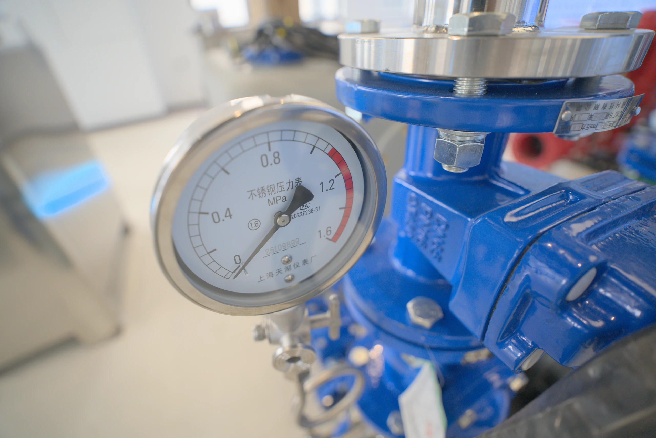
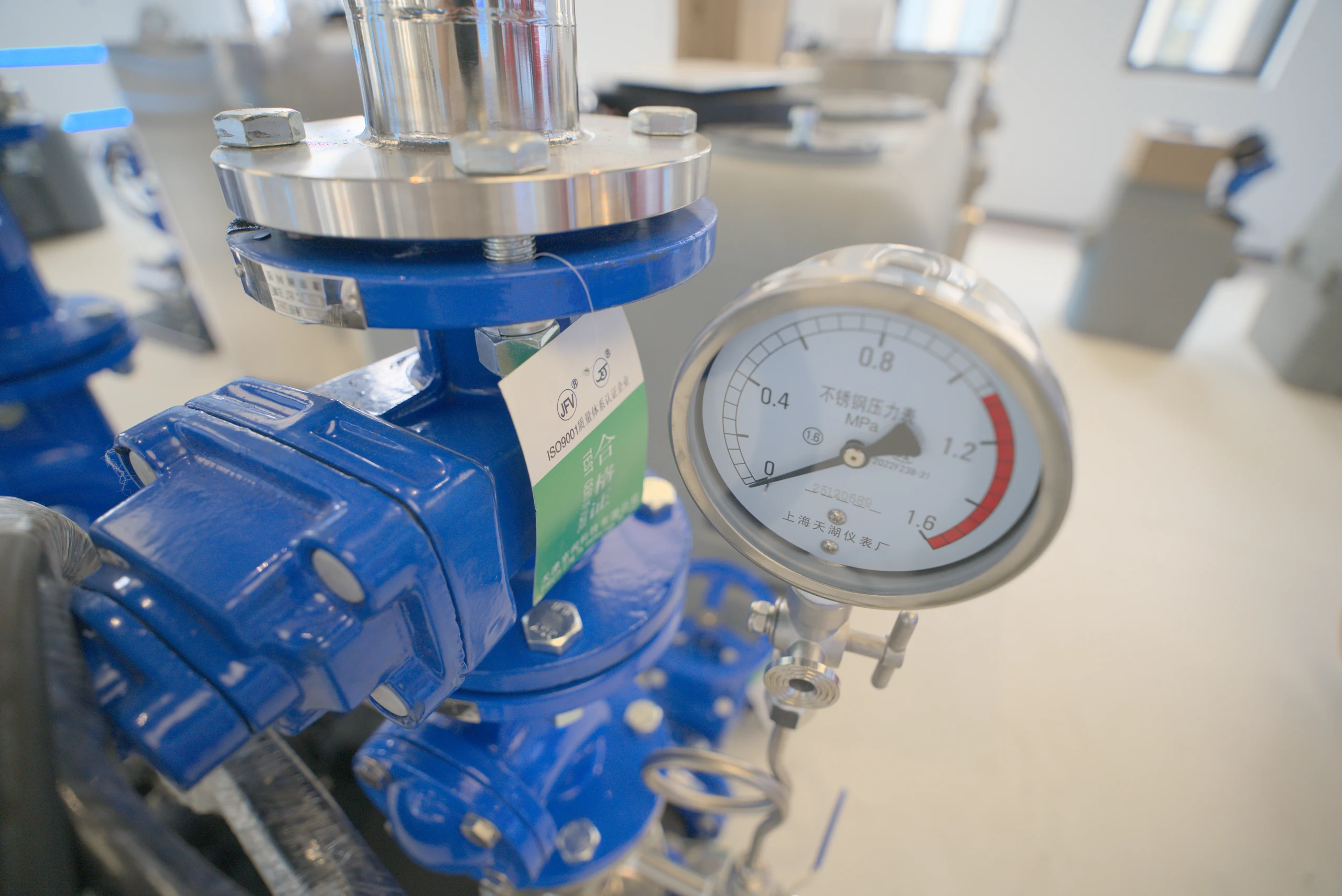
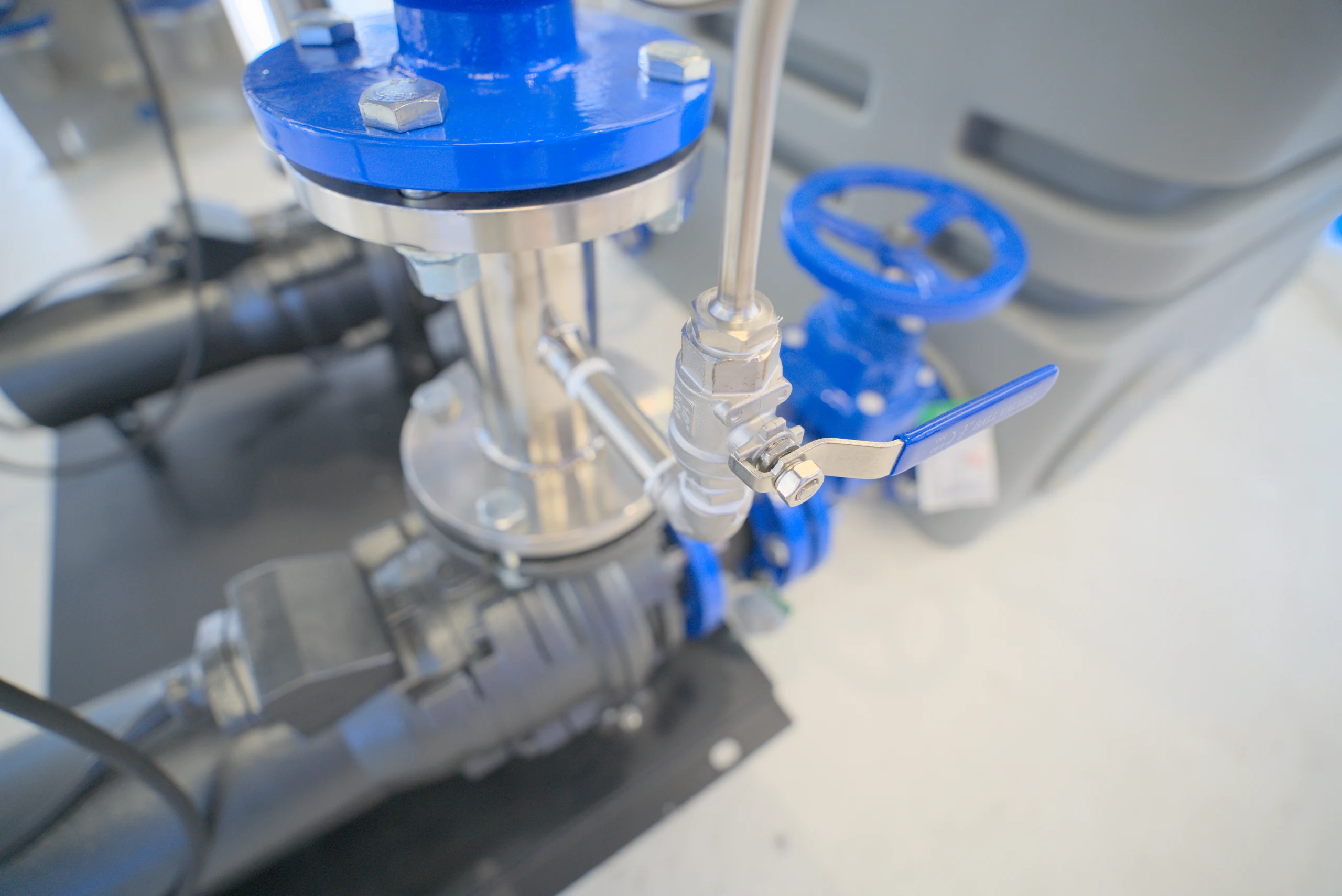
Check valves and gate valves are installed in the pipeline behind the pump, and the upper outlet pipes merge. Each connection node is clearly visible, making it easy to check the status of pipe valves; the specific valve and instrument configurations are determined according to the selection plan.
There is capacity for collecting water. The has an orderly layout.
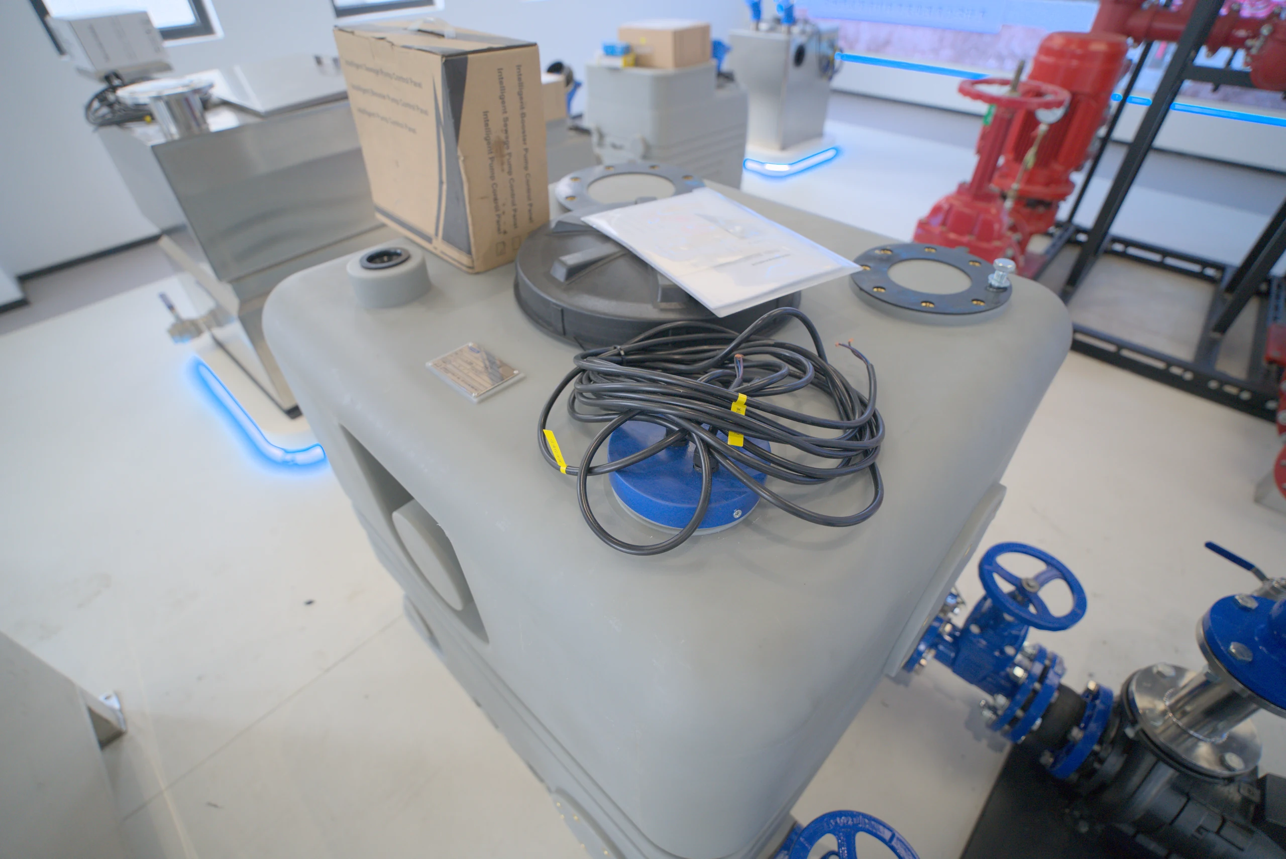
The PE box is responsible for sewage collection, and the external stiffeners form a clear structural outline. The top access opening and multiple interfaces provide operating space for inspection, takeover and on-site layout.
PE boxTop inspectionMultiple interfaces
04 / Pump front connection
From the box to the pump set. connections are clearly visible.
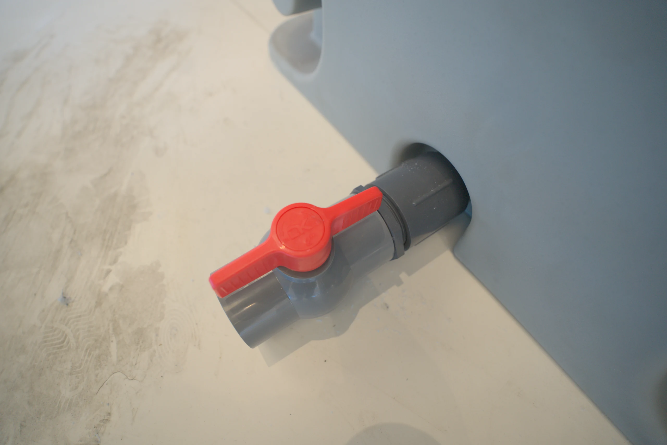
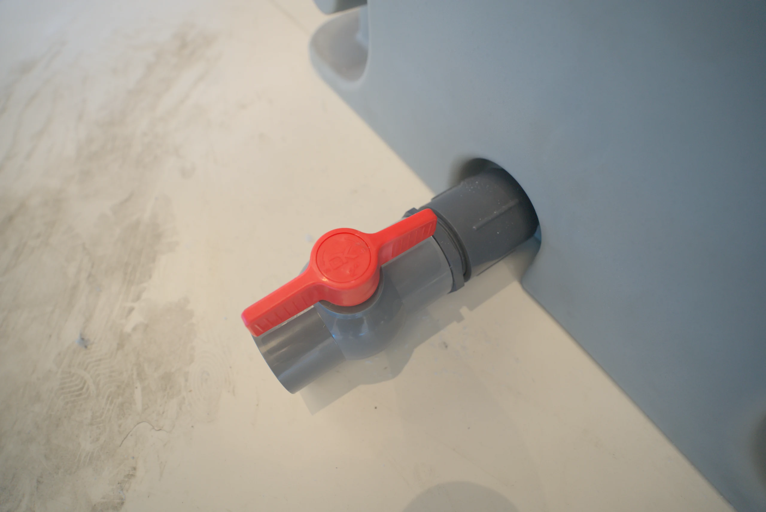
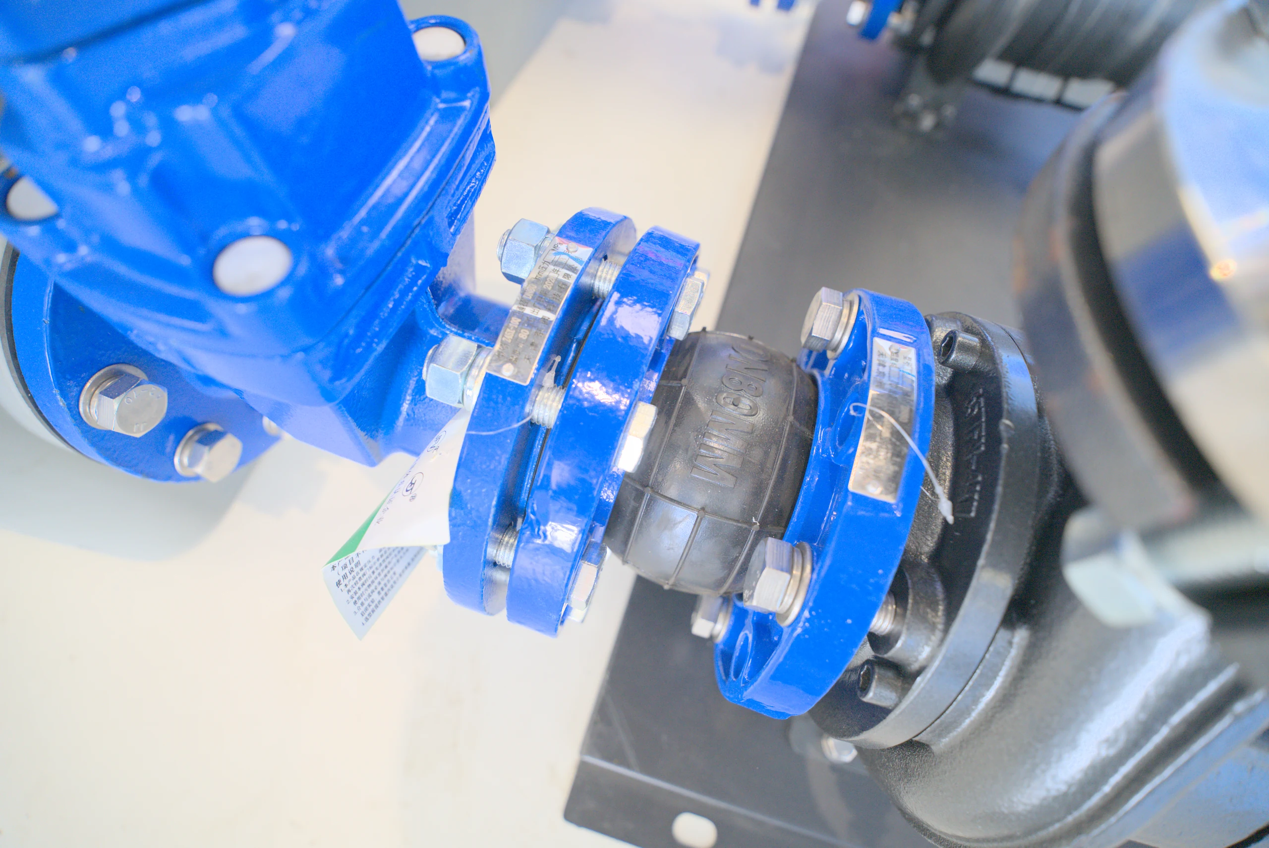
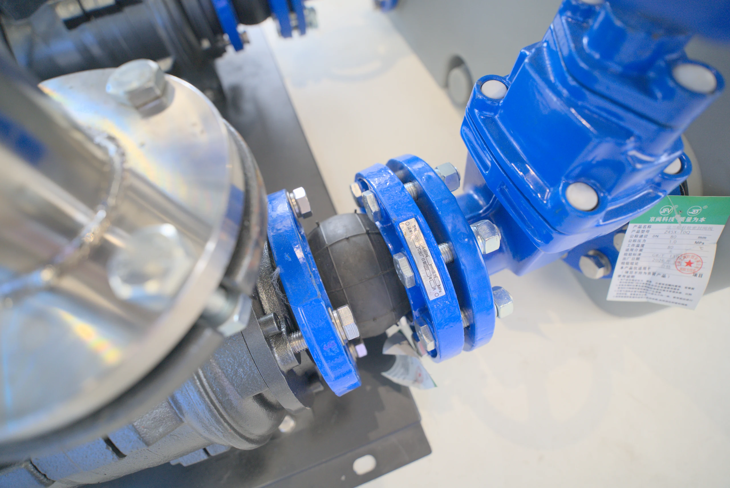
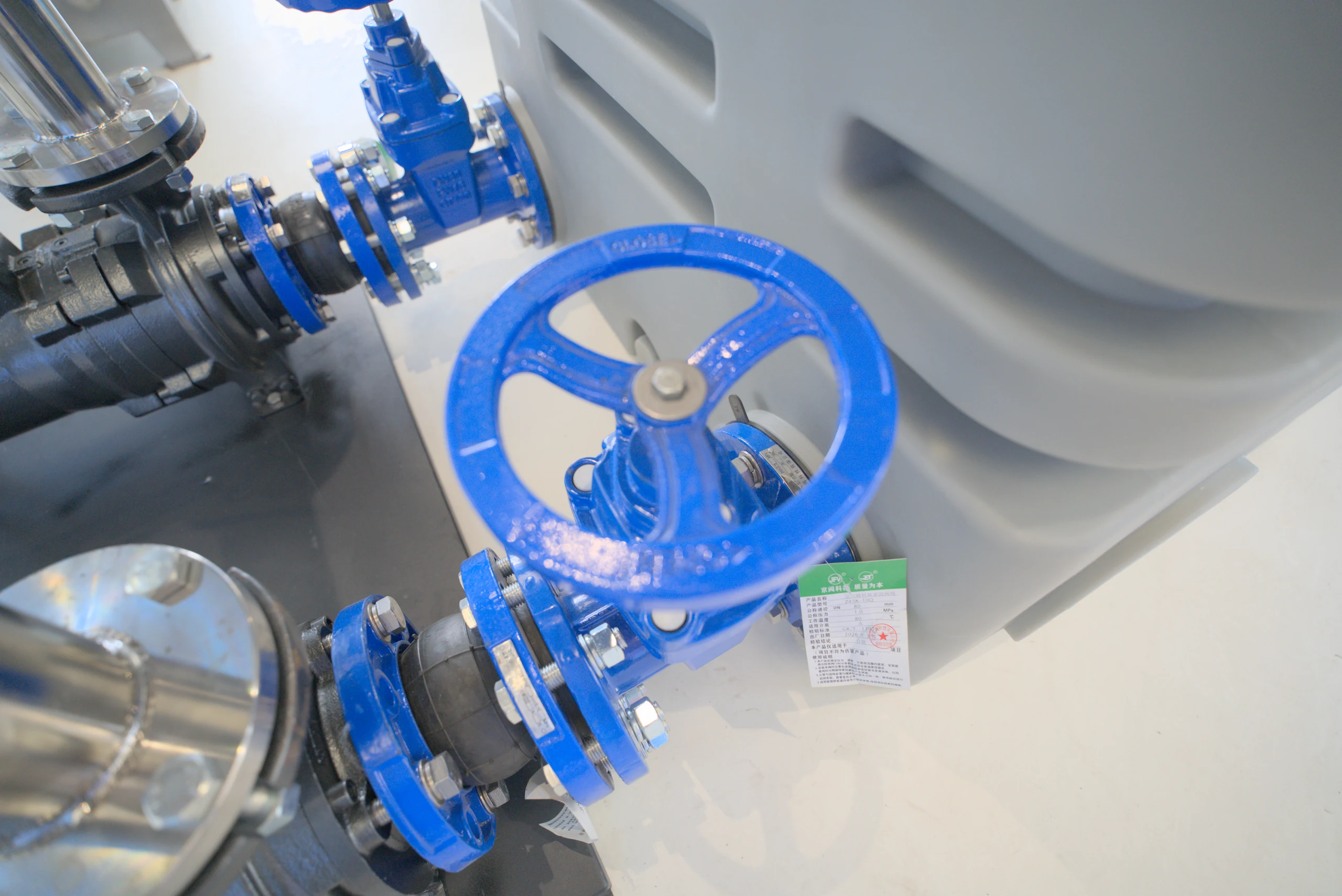
The box and the external pump are connected through pipelines. The structural diagram of the sample booklet marks the PVC gate valve and rubber soft joint, and the actual factory photos also show the valve and flange connection details.
Pump front valveSoft connectionConfigure on demand
Product structure diagram; pump type, valve and connection form are subject to the selected configuration.
01Pump set externalThe operating position is clear at a glance+
The pump body and connecting nodes are located outside the box for easy access and inspection. When laying out, reserve maintenance space according to the disassembly and assembly direction of the pump body.
02Pipe valve integrationFrom connection to water outlet, orderly arrangement+
The connection in front of the pump, the valve group behind the pump and the outlet pipe are arranged in complete sets. During maintenance, stop the machine according to the operating procedures and confirm that the corresponding pipelines have been isolated.
03Multiple volumeAdapt equipment to project needs+
The sample catalog provides three volumes of 250L, 500L, and 1000L, including different flow rates, lifts, and power configurations. The selection is completed based on site conditions.
02 / CAPACITY MEETS PURPOSE
Different needs. Same in order solution.
Select a volume to view typical configurations in the catalog. Let selection start with clear data.
PWT
PE pump external series Series appearance diagram, non-capacity size comparison
The three sets of configuration examples in the external pump series catalog do not represent all configurations of each volume.
Volume/L
Device model
Flow / m³/h
Lift/m
Power/kW
Overall dimensions/mm
Voltage/V
water inlet
water outlet
250 ●
PWT250V15-15-1.5TW2P
15
15
1.5
1680 × 868 × 1150
380
DN100
DN50
500 ●
PWT500V25-27-4TW2P
25
27
4.0
1925 × 1010 × 1150
380
DN100–150
DN65
1000 ●
PWT1000V55-32-7.5TW2P
55
32
7.5
1925 × 2140 × 1150
380
DN100–150
DN65
Data source: "Grease Separator and Sewage Lifting Product Catalog" Pump External Series, printed pages 13–14. The above are three typical configurations, not the performance range of each volume; there are other configurations for the same volume. The specific working points and equipment dimensions are confirmed by project selection.
Good layout. Let every maintenance go one step further.
From the box to the pipe valve, from the pump set to the base. Pay attention to the equipment, but also pay attention to the people using the equipment.
You can see the structure clearly. Leave room for maneuver.
The external design allows the pump set and pipe valves to be directly outside the box. When installing the equipment, plan a suitable maintenance space based on the disassembly and assembly of the pump body, valve operation and top opening direction.
01Box water collection→02Pump set upgrade→03Pipe discharge
Selection and site layout +
Provide the design drainage volume, lifting height, pipeline length, available space and power supply conditions to determine the corresponding configuration. During installation, confirm the foundation, ventilation, water inlet and outlet interfaces and maintenance locations. Renderings, sample book structures, and actual equipment accessories may differ depending on configuration.
04 / PRODUCT PHOTOS
Product photos, details are visible.
From the whole to the details, get a closer look at the product. Click on the image to enlarge it.
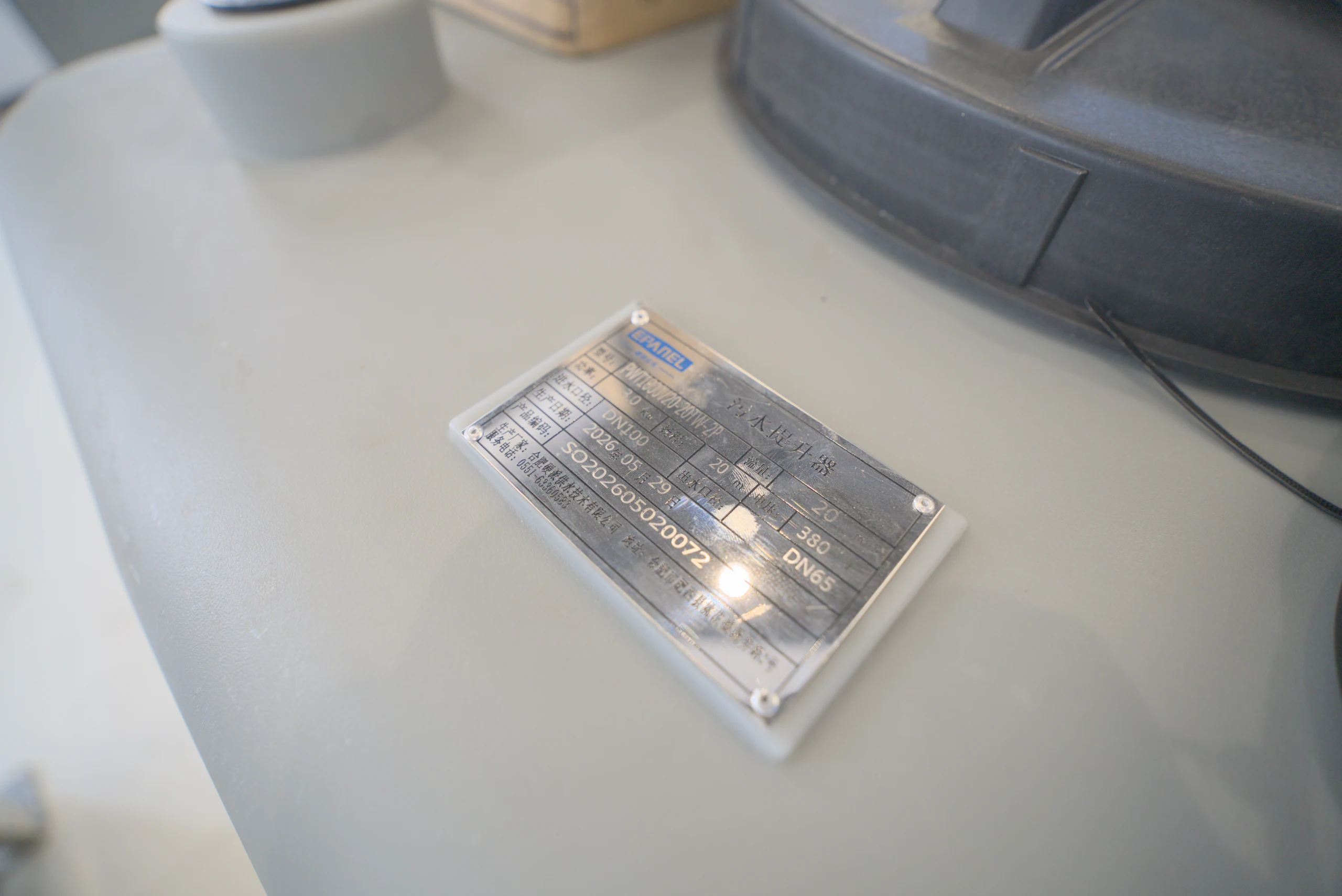
Real photography · 34 ZhangThe details of the external pump unit, box and pipe valves present the real manufacturing site from multiple angles.


 Back