Back
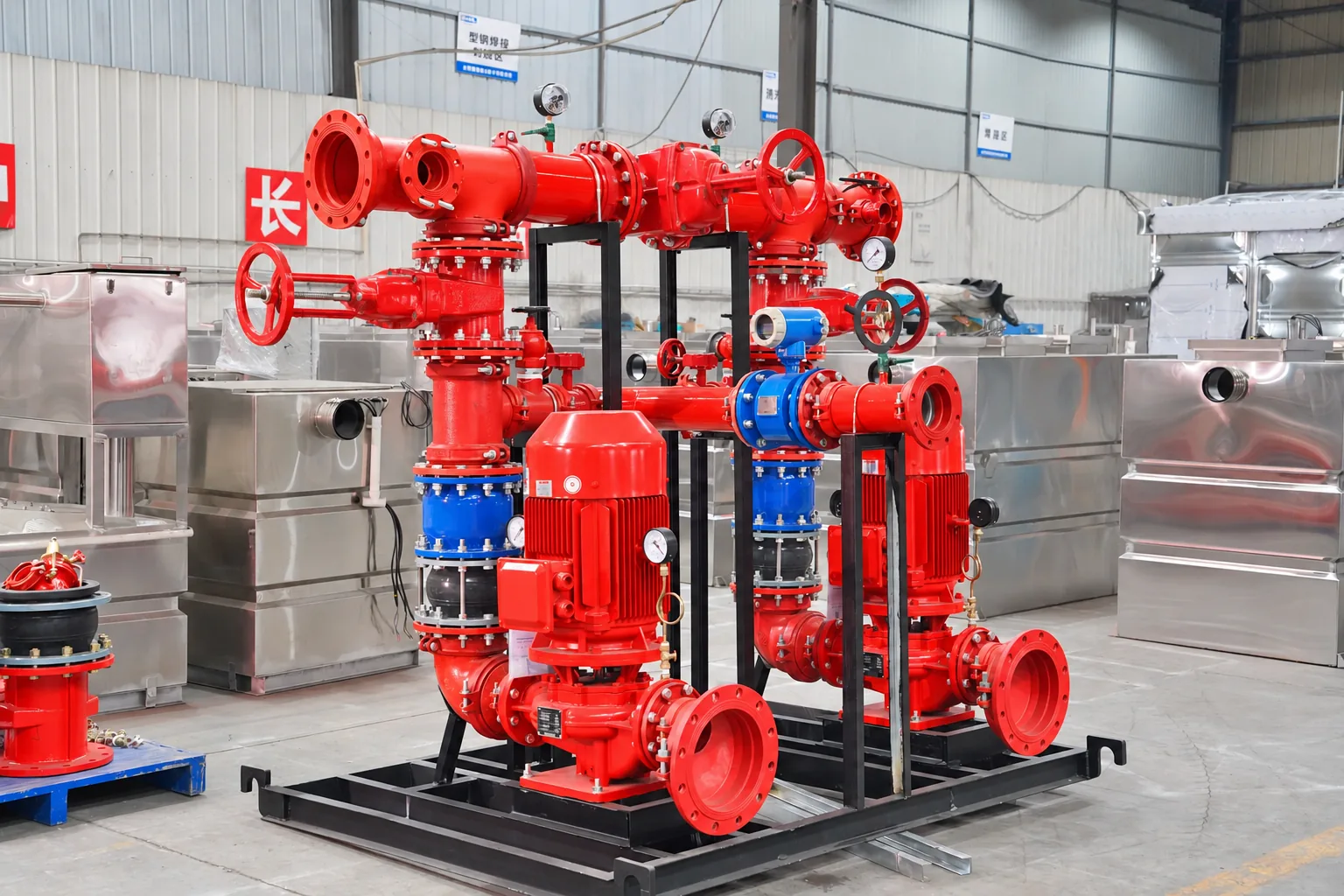
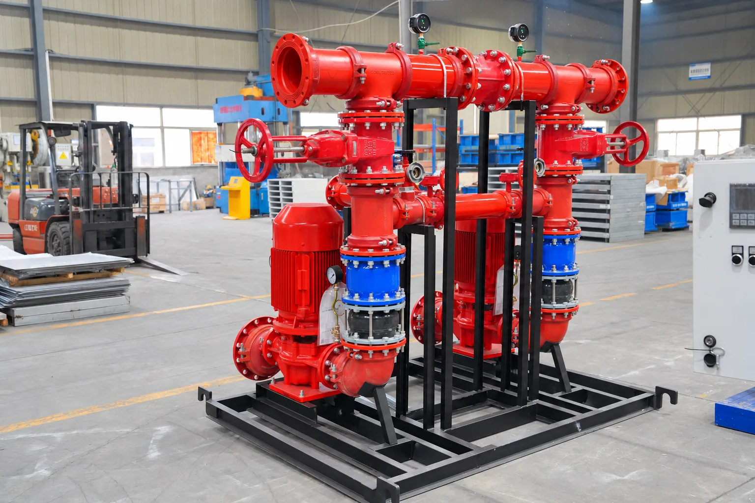
fire pump unit
Based on the design flow, head and system form, determine the combination of main pump, backup pump and voltage stabilizing device.


EPANEL / INTEGRATED FIRE PROTECTION
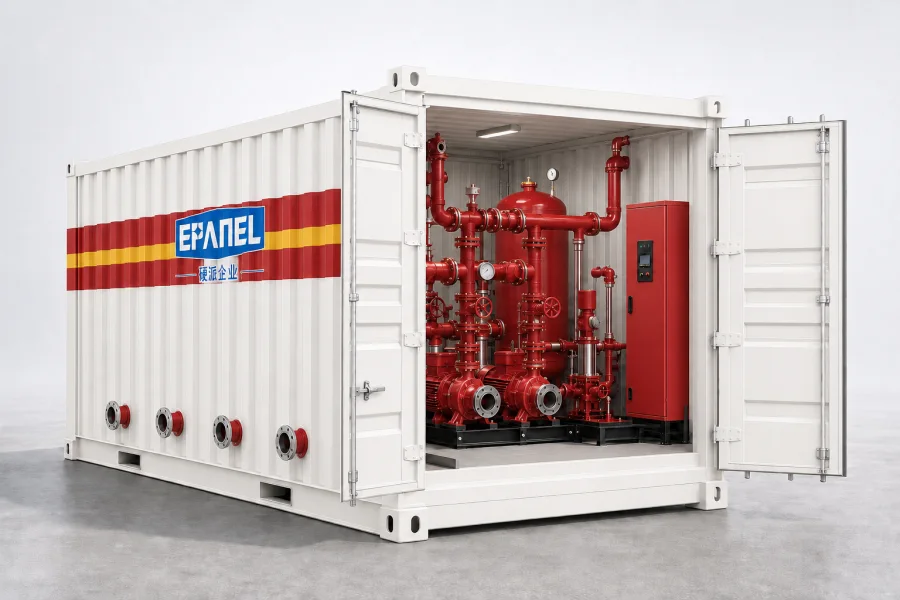
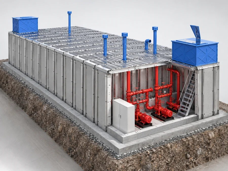
Factory prefabricated. Delivered as a set.
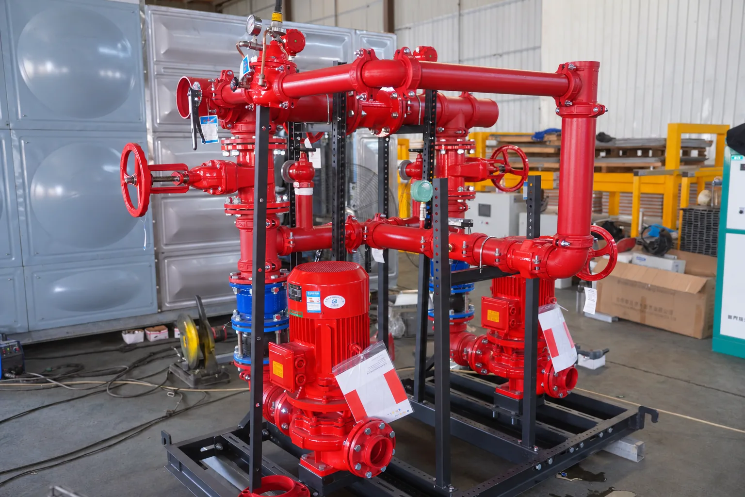
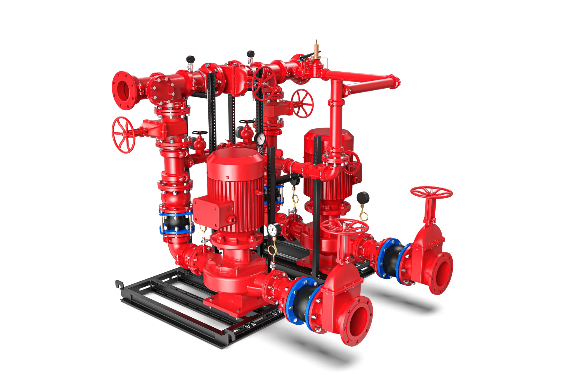
Integrate the fire pump set, pipeline valve set and electrical control into a common base, and move the design, piping and assembly forward to the factory, so that the equipment and the site can be connected in an orderly manner.
Factory integration/interface coordination/visual operation and maintenance
01 / SYSTEM COMPOSITION
From equipment layout to field interfaces,
Organize scattered components into a complete system.
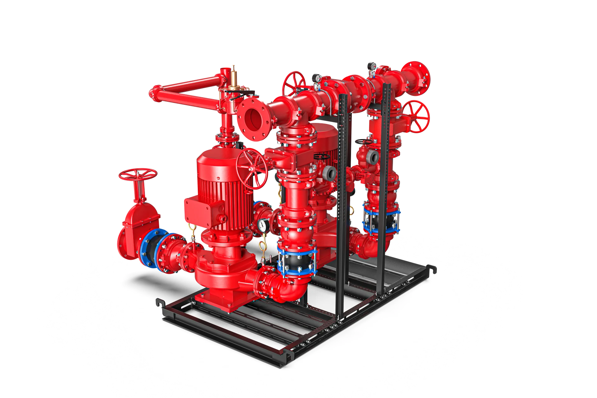
Based on the design flow, head and system form, determine the combination of main pump, backup pump and voltage stabilizing device.
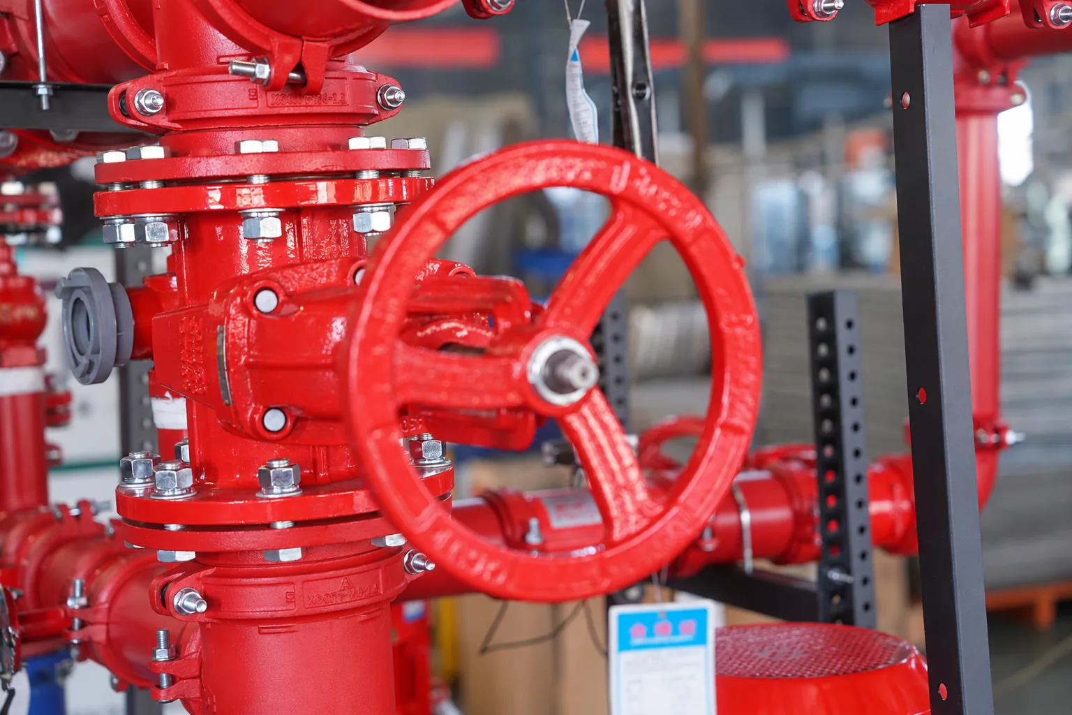
Coordinate the water suction and outlet main pipes and valve components, and clarify the interface direction, caliber and instrument connection location.
Combined with the power supply conditions and fire protection linkage requirements, the control cabinet, local operation and signal interfaces are configured.
Access pressure, liquid level, valve position and equipment operation information by project to connect on-site viewing and status feedback.
Use shaped steel skids and brackets to organize the equipment layout and coordinate the space for fixing, hoisting, installation and maintenance.
Access platform status, current alarms and videos on demand, and confirm functions and permissions in combination with projects.
The above are combinable system units. The specific pump type, quantity, configuration and supply scope are subject to the project technical plan.
water supply pathWATER FLOW
02 / CONNECTED OPERATIONS
Instrument collection and platform display are connected.
Provide information for device viewing and anomaly checking.
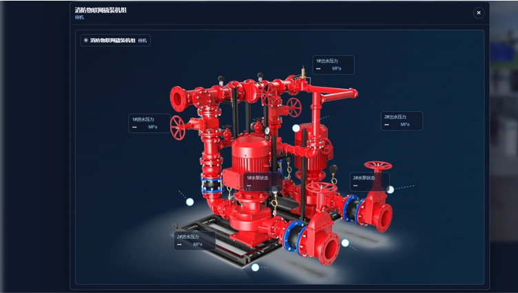
The platform screen is a screenshot of the information. The actual functions are subject to the project configuration, access point, network conditions and account permissions; the startup method, switching logic, linkage conditions and pressure setting values are confirmed according to the project design.
03 / BUILT BEFORE ARRIVAL
From deepening to manufacturing,
Let every delivery link have evidence to follow.
The piping, assembly and wiring arrangements are completed in the factory, and the on-site focus is on equipment placement, interface connection and system joint debugging.
Combined with the deepening of machine room size, pipeline direction and control requirements, the configuration and supply boundaries are clarified through a complete list.
Connect the three-dimensional layout check, unified assembly and factory inspection, and review the equipment layout, markings and accompanying materials.
Consider valve operation, equipment maintenance and status checking during the layout stage to make the connection between installation and daily management clearer.
Application directionAPPLICATIONS
05 / PROJECT DELIVERY
Confirm the requirements first, and then deepen the configuration.
Let design, manufacturing and installation be connected in an orderly manner.
Clarify the flow head, system form, machine room conditions and scope of supply.
Check equipment layout, pipeline interference, interfaces and maintenance space.
Check BOM, equipment selection and professional interfaces.
Complete the base, piping, valve group, wiring and marking.
Check equipment, linkage, signs and information according to technical protocols.
Arrange in place according to the contract, take over wiring, joint debugging and disclosure.
06 / CONFIGURED FOR YOUR PROJECT
Provide project conditions,
Make selection, interfaces and scope of supply clearer.
| Flow and head | Design flow, head, system form and fire water supply zoning |
|---|---|
| Pump set combination | Main and backup pump configuration, voltage stabilization requirements and drive form |
| Pipe interface | Water inlet and outlet diameter, direction, elevation and external connection conditions |
| Computer room conditions | Available dimensions, foundation, transportation, hoisting and operation and maintenance space |
| Electrical and Networking | Power supply, linkage signals, monitoring points and network access requirements |
| environment and delivery | Environmental, anti-corrosion requirements and supply boundaries for equipment, drawings and services |
The equipment layout can be deepened based on the size of the machine room, the direction of water inlet and outlet, and maintenance requirements. Whether it is transported as a whole or delivered in modules, the transportation route, hoisting conditions and on-site interfaces need to be confirmed at the same time.
IoT capabilities are configured on a project-by-project basis. It is necessary to clarify the monitoring point location, control logic, on-site network and account permissions, and provide status viewing, alarm or video functions according to the confirmed access range.
The site must have the installation foundation and supporting conditions, and complete the installation of equipment, external pipelines, power supply and signal connections. System joint debugging, training briefings and service scope are subject to the technical agreement and contract.
TALK TO EPANEL
Contact the EPANEL team to discuss the configuration and delivery plan of the firefighting skid-mounted unit.