Back
EPANEL / PLRC PREFABRICATED PUMP STATION
underground concretePrefabricated pump room
Factory prefabricated and on-site assembly.
Made of reinforced concrete precast components and HDPE corrosion-resistant composite lining,
Build underground fire pools and pump rooms to coordinate water storage, water supply and ground space.
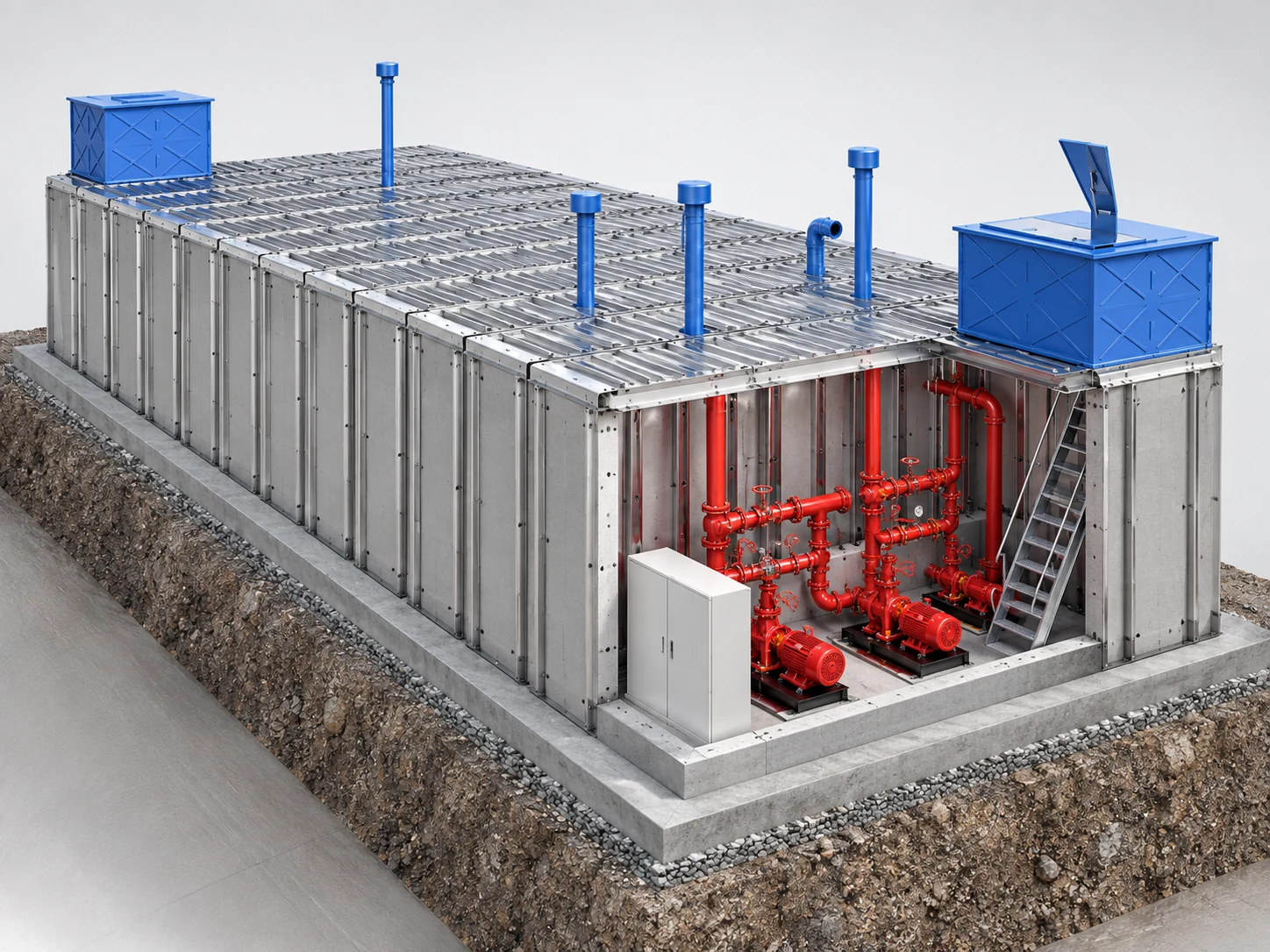
Structure and lining composite
Reinforced concrete load-bearing, HDPE water protection
Main components factory prefabricated
Beam, column and side panel modules are connected to on-site assembly
Equipment is arranged underground
Plan ground use based on covering soil conditions
01 / INSIDE THE STRUCTURE
From a side panel,
to a complete pumping station.
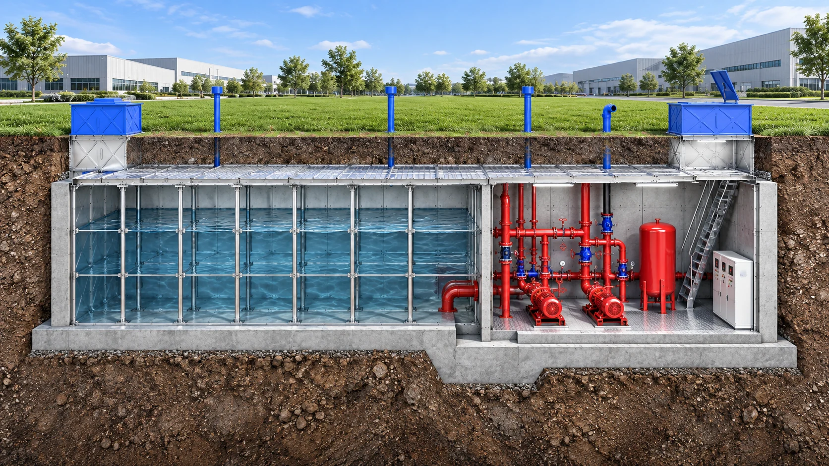
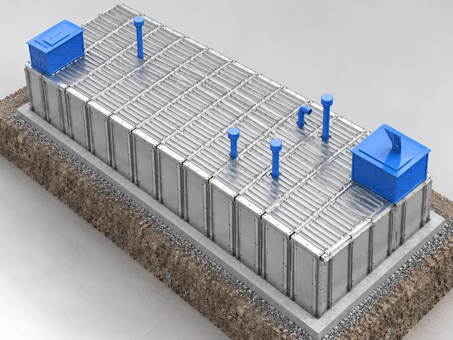
The pool, pump room and top supporting facilities are arranged in a coordinated manner.
Select a system unit to understand its structure and function.
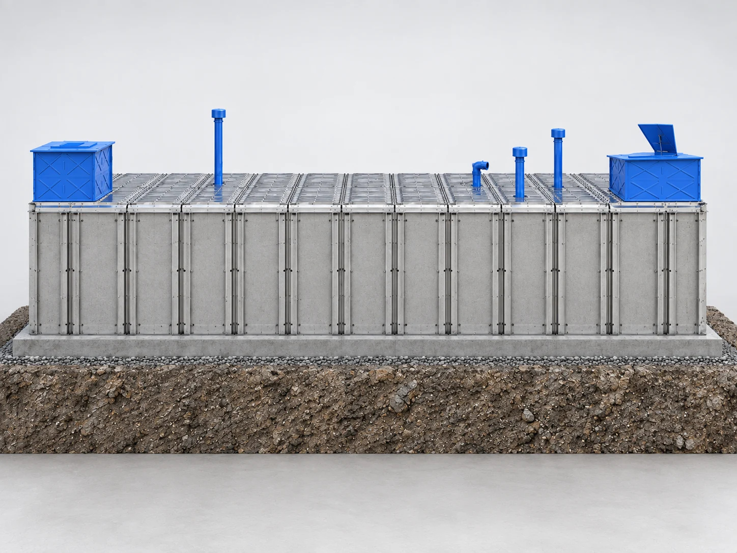
COMPOSITE WALL
Concrete bearing capacity. HDPE faces water.
The side panels are made of reinforced concrete anchored with HDPE hard corrosion-resistant resin. During prefabrication, the lining is combined with the structural layer, the HDPE corrosion-resistant layer is used on the water surface, and the plate connection and joint waterproofing jointly form the pool body.
WATER STORAGE
Make water storage space suitable for the site.
The pool module is organized according to the effective water storage capacity and the site plane, and is arranged in coordination with the pump room. The positions of water inlet, water suction, overflow, emptying and liquid level monitoring are uniformly confirmed in the detailed design.
PUMP ROOM
Arrange equipment and maintenance space together.
Fire pump units, pressure stabilizing devices, pipeline valves and control equipment are centrally arranged in the pump room. Select the type according to the design flow, head and system partition, and reserve operation and maintenance channels at the same time.
ACCESS & VENTILATION
After being buried underground, it is still easy to maintain.
The maintenance entrance, ventilation and top accessories shall be arranged in a coordinated manner with the site elevation. Confirm the location of the entrance based on the drainage and equipment transportation requirements of the pump room, and review the roof, beams and covering soil conditions according to the structural design.
02 / BELOW GROUND. ABOVE POSSIBILITIES.
Place equipment underground.
Leave the ground to the project.
Ground uses such as greening, walking, parking or roads,
Plan jointly based on load and covering soil conditions.
Determine the purpose of the ground first
Confirm greening, road or parking needs based on the general plan, and then deepen the layout of underground equipment.
Check the carrying conditions item by item
Vehicle load, soil cover thickness, groundwater and anti-floating requirements jointly affect the beam, column and roof plan.
Maintenance channel synchronization design
Incorporate access openings, ventilation, drainage and transportation conditions into the design so that subsequent operation and maintenance can be based on evidence.
The passing plan must be calculated and confirmed based on the actual vehicle load, soil thickness and structure. The illustrations are only used to show the spatial relationship.
03 / FROM FACTORY TO SITE
Manufacturing is forwarded to the factory.
The device is connected to the site.
Use real construction photos to present the main processes.
The construction sequence and nodes are subject to the project plan.
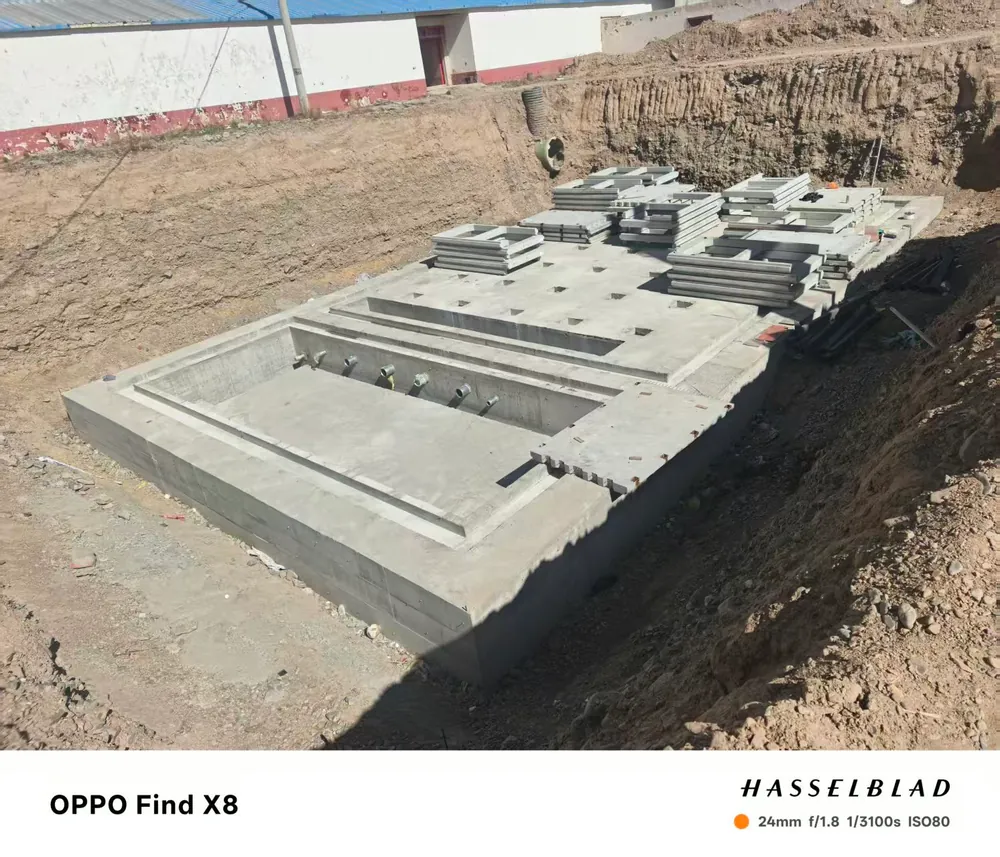 01
Basic production
Review the geology, groundwater and anti-floating conditions, and complete the foundation pit and foundation.
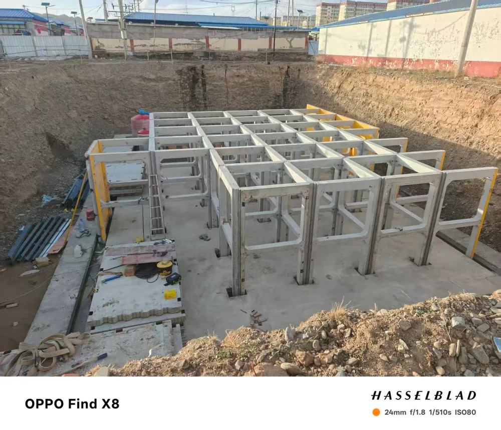 02
components in place
Verify prefabricated components, position and install beams, columns and side panels.
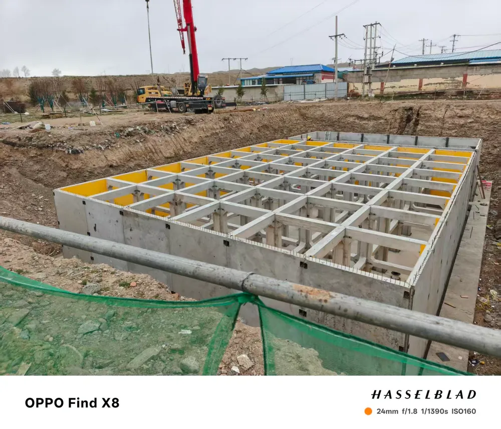 03
Connectivity and waterproofing
Complete the connection, secondary pouring of the trench and waterproofing of the joints.
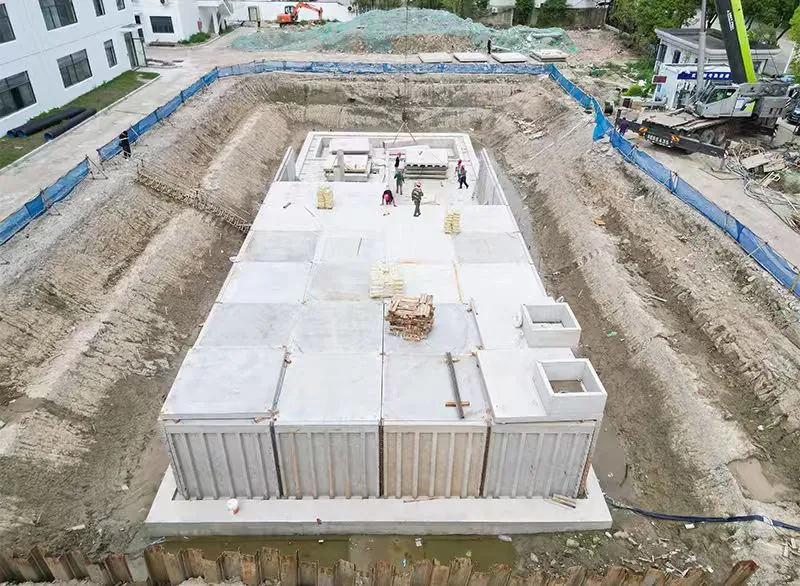 04
Top plate and accessories
Complete roof panels, access entrances and ventilation accessories as designed.
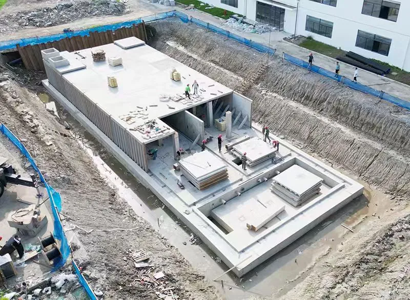 05
Equipment and Inspections
Connect pump units, pipelines and controls, and organize full water testing and debugging.
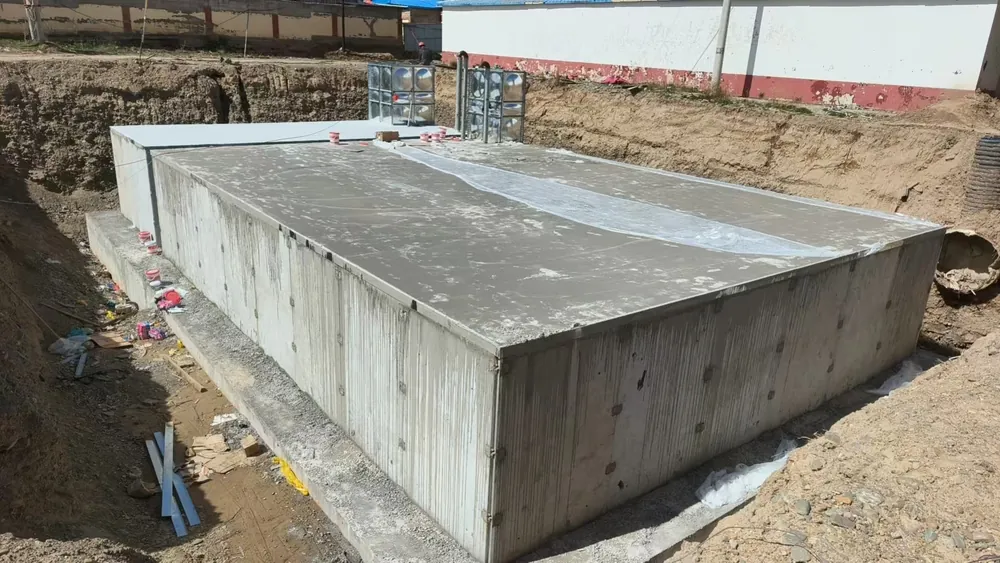 06
Backfill and Delivery
Backfill according to the confirmed plan and complete the handover of site restoration and maintenance data.
04 / REAL CONSTRUCTION. REAL DETAILS.
Go into the construction site.
See every step of the assembly.
Original project photos, retaining the true construction status.
Click to view HD details.
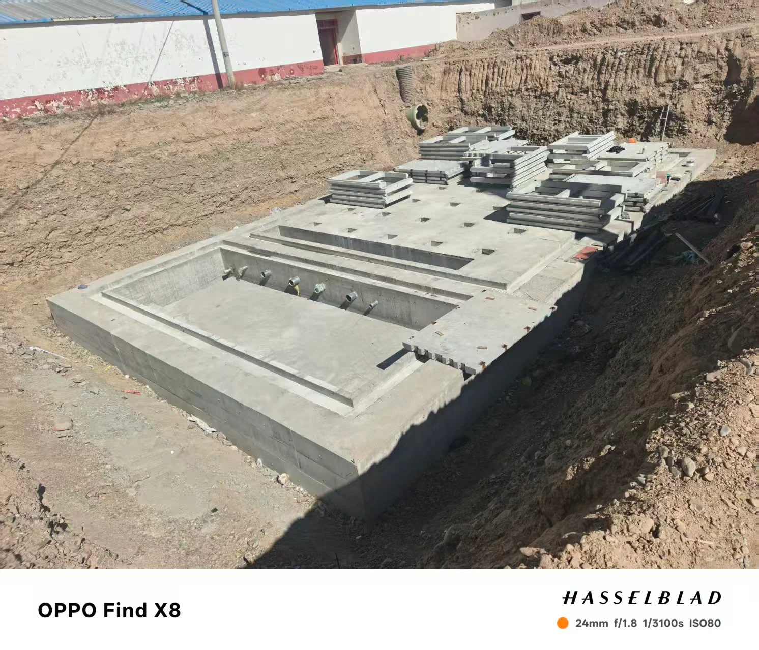
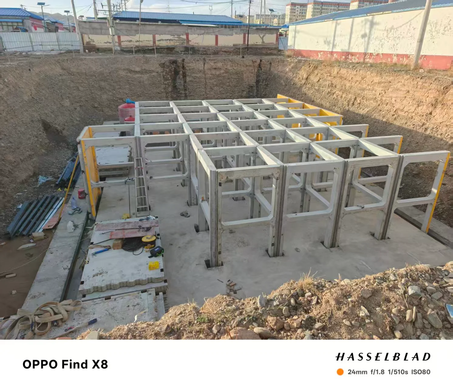
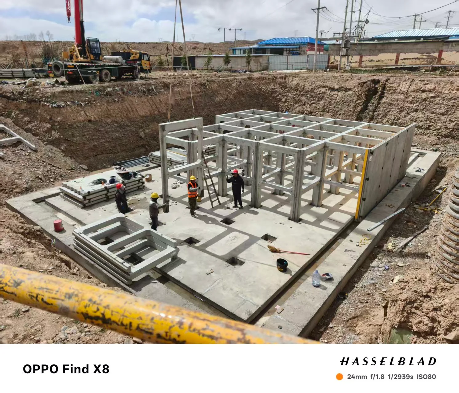
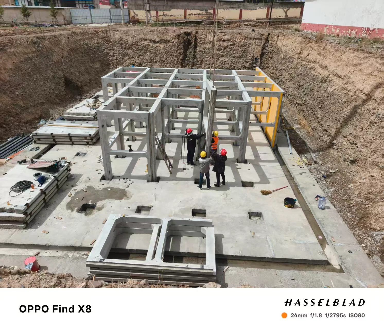
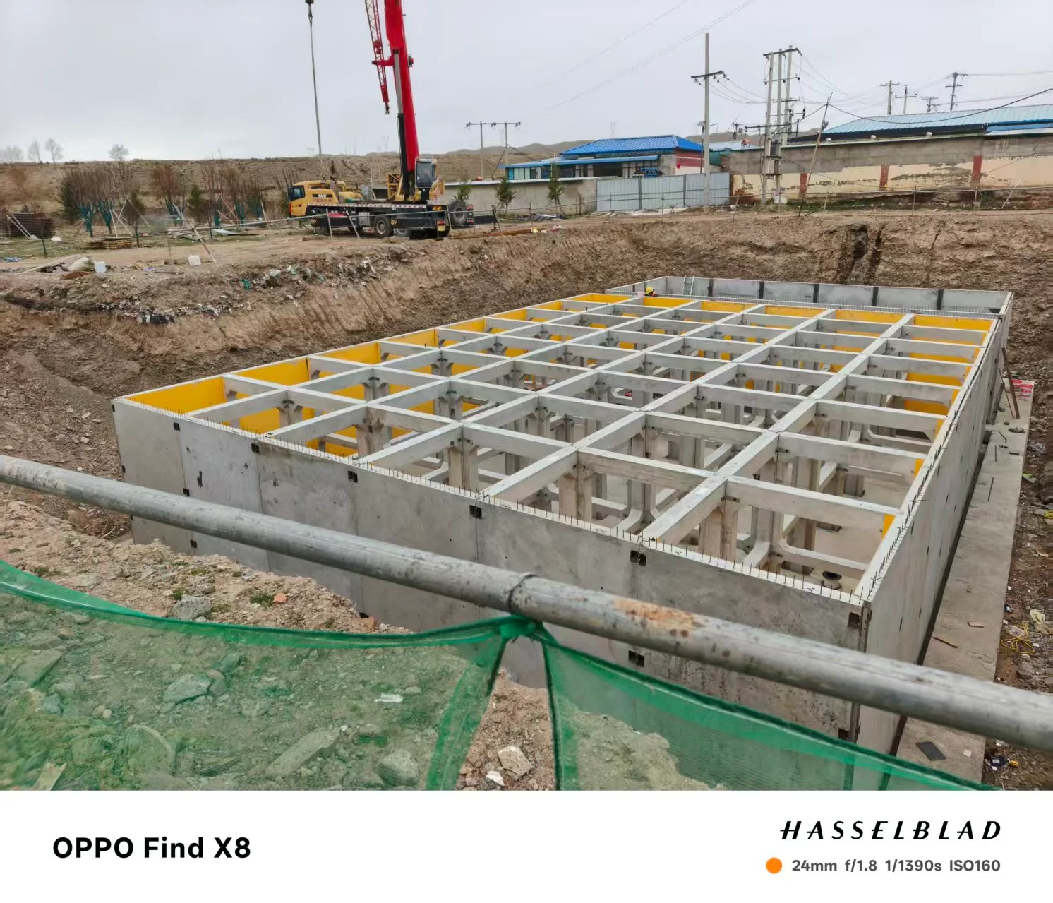
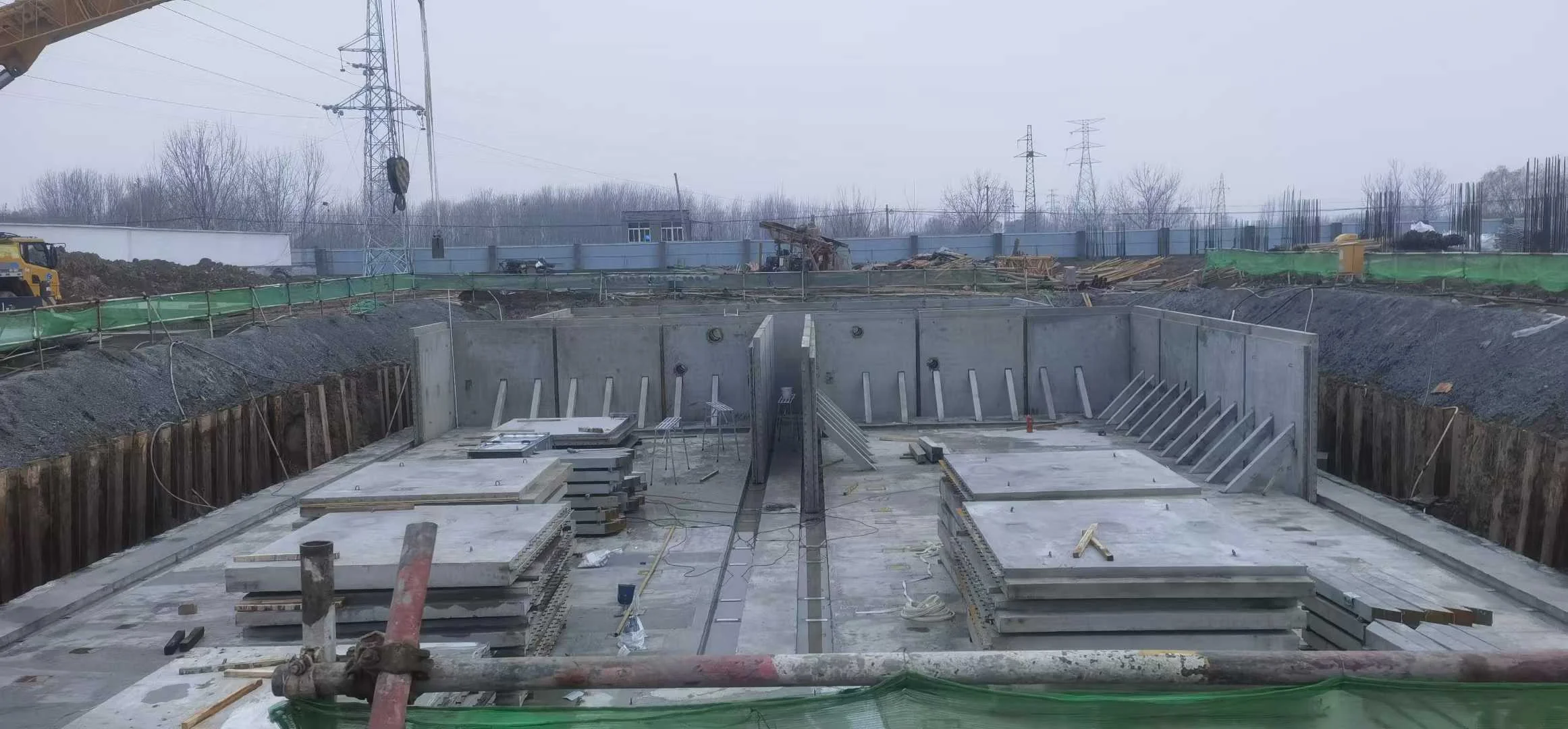
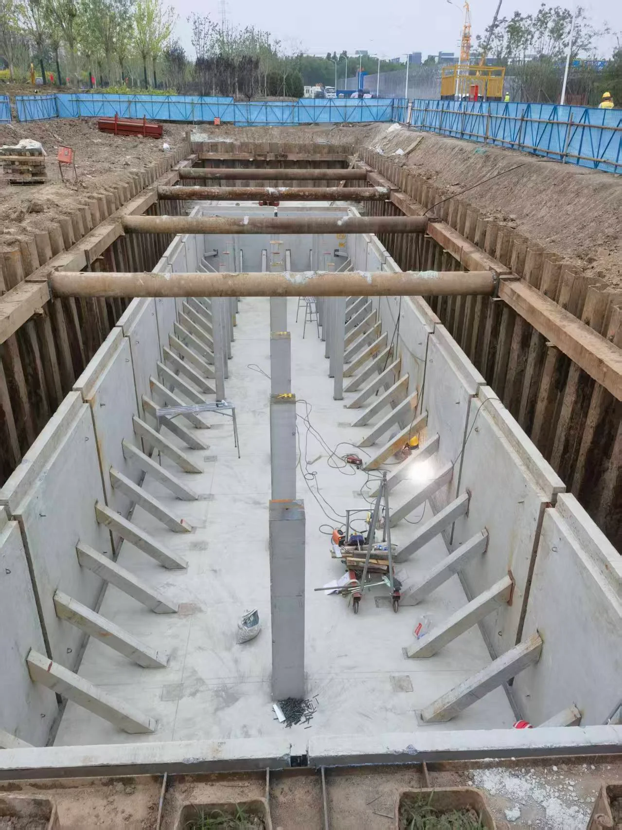
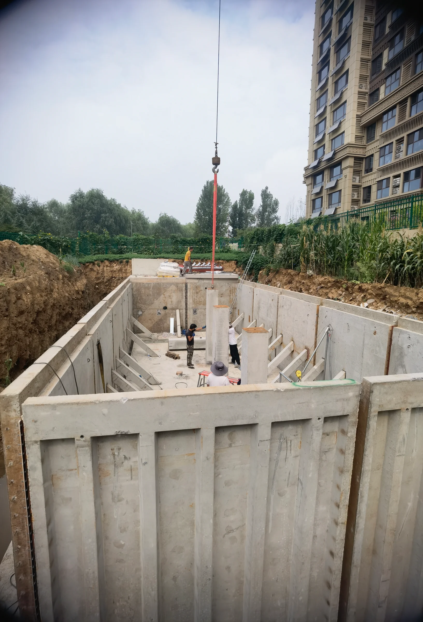
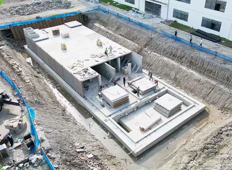
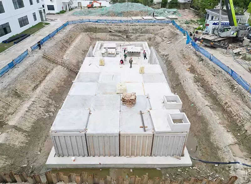
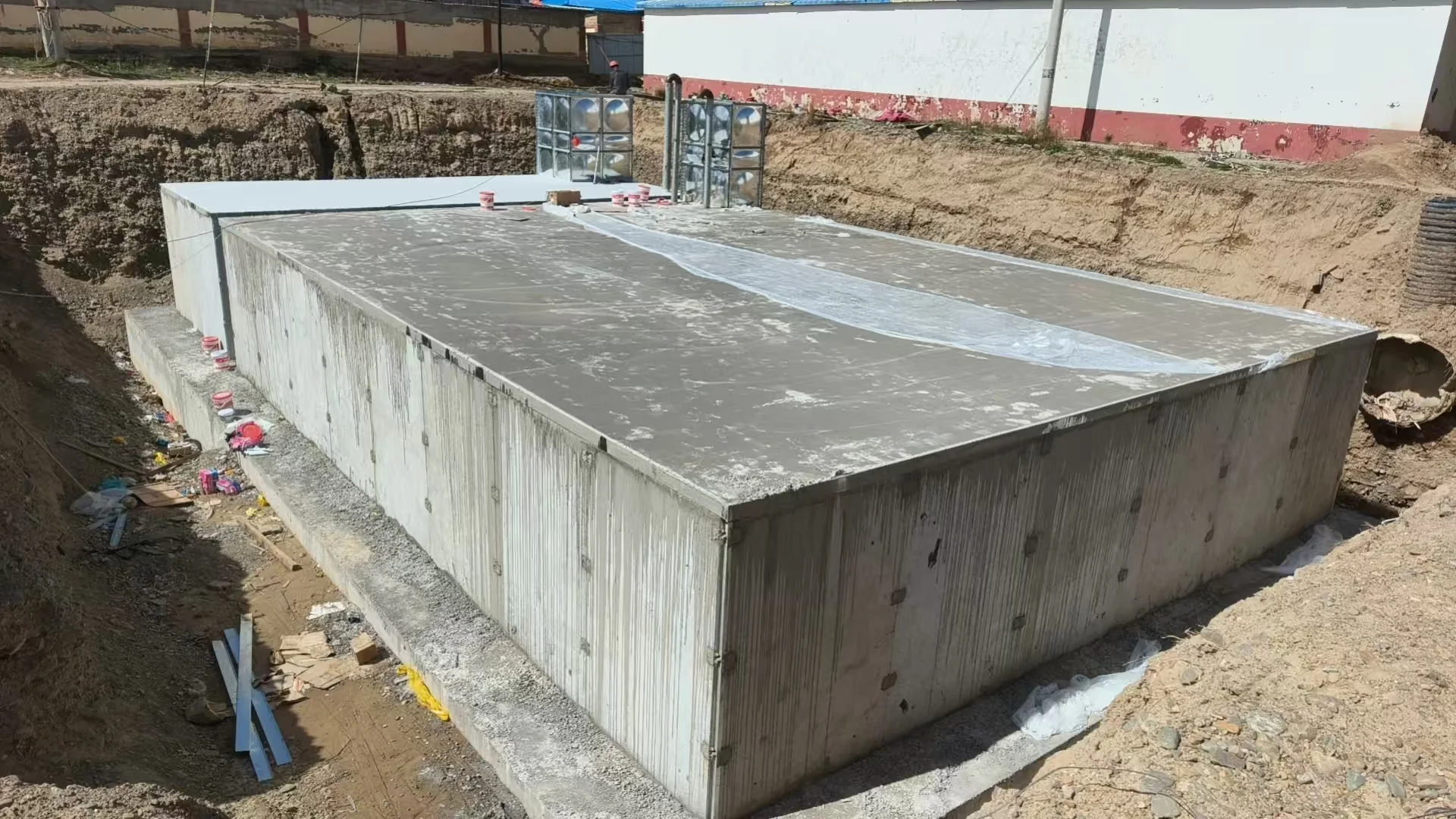
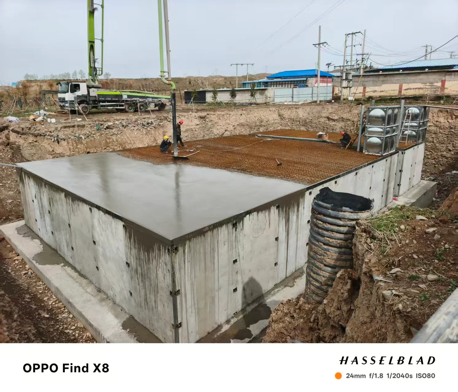
Hover to pause · Directional key switching · Swipe to browse · Click to enlarge
Photos are only corrected for orientation, proportionally scaled and compressed, retaining the original image. The pictures show different construction stages, and the configuration and working conditions vary from project to project.
05 / ENGINEERED FOR YOUR SITE
A suitable plan,
Start with specific conditions.
After the water storage needs and fire protection conditions are clear,
Then connect the structure, equipment and field interfaces one by one.
Configuration and Selection Key Points
| Product system | PLRC prefabricated reinforced concrete joint corrosion-resistant module fire pump station |
|---|---|
| pool wall structure | Reinforced concrete precast components + HDPE anchored composite lining |
| water storage capacity | Designed according to effective fire water storage capacity, plane size and water level conditions |
| Pump set configuration | Design flow, head, main and backup pumps and voltage stabilization requirements are confirmed according to the project |
| Underground working conditions | Covering soil thickness, ground load, geology, groundwater and anti-floating review |
| Engineering interface | Pipeline elevation, power supply, control linkage, ventilation, drainage and maintenance conditions |
The specific dimensions, load capacity, equipment parameters and scope of supply are subject to the technical plan confirmed by both parties.
01Applicable scenarios+
It can carry out program demonstration for the fire protection supporting needs of industrial parks, energy storage, wind power, photovoltaic and public construction projects. The applicability needs to be confirmed based on the fire protection design and site conditions of each project.
02What do you need to provide in advance?+
The overall site plan, effective water storage capacity, design flow and head, groundwater level and geological survey data, ground uses and loads, as well as external pipelines and power supply conditions.
03How to determine the passing plan+
Review the roof, beams, columns, pump room support and foundation plans based on the actual vehicle load and covering soil thickness, and organize the ground layout based on the location of the inspection opening.
04How to connect delivery and maintenance+
From prefabricated component verification, on-site installation to full water test, equipment debugging and data handover, it is organized according to the confirmed plan; maintenance, ventilation and drainage conditions are retained to facilitate subsequent inspection and maintenance.
EPANEL / ENGINEERING SUPPORT
Let the underground space
Taking care of your fire water supply needs.
Provide site conditions and fire protection design requirements,
EPANEL will work with you to deepen the structure and equipment plans.