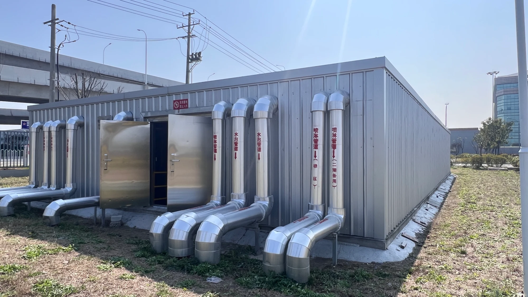
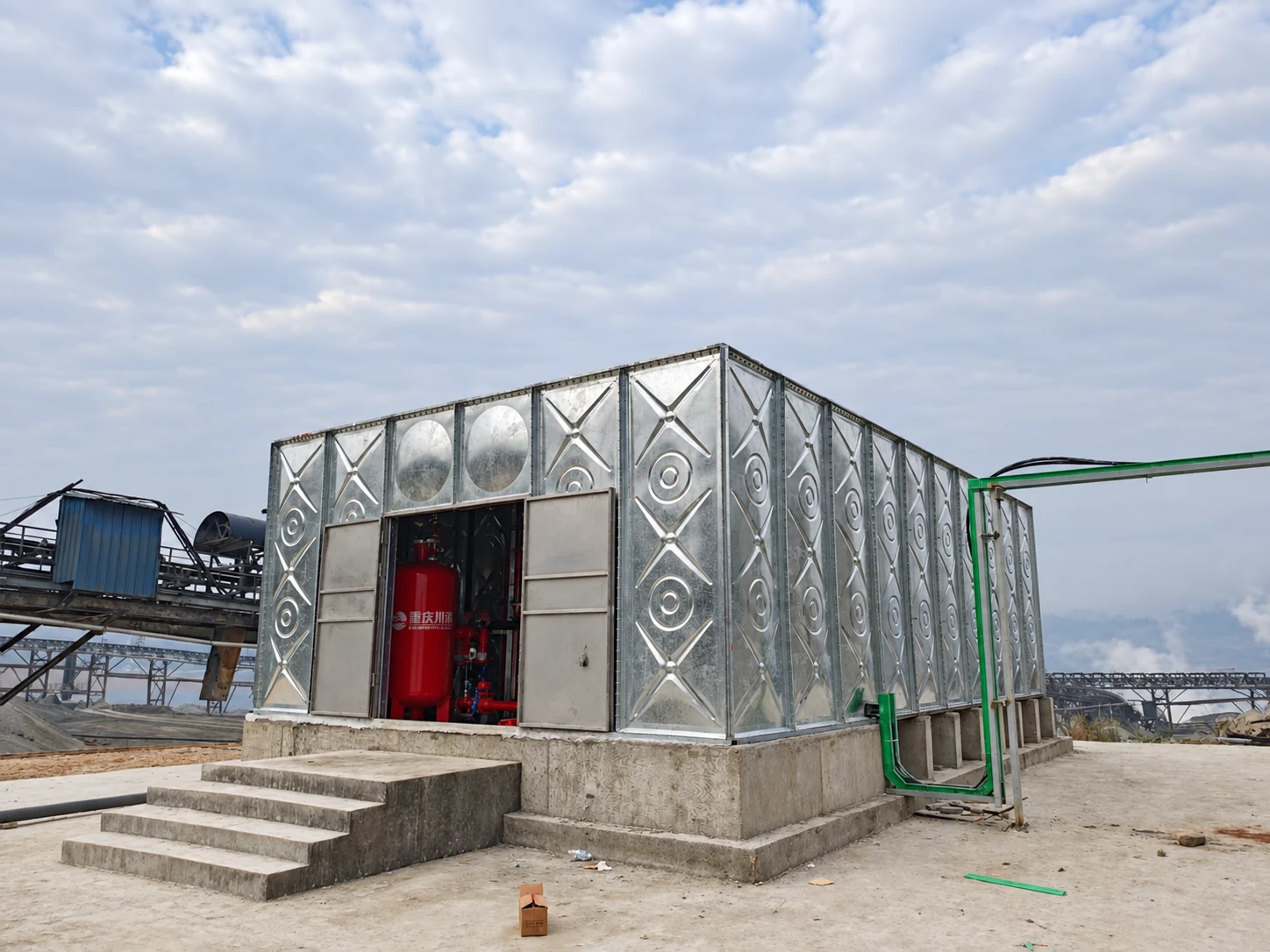
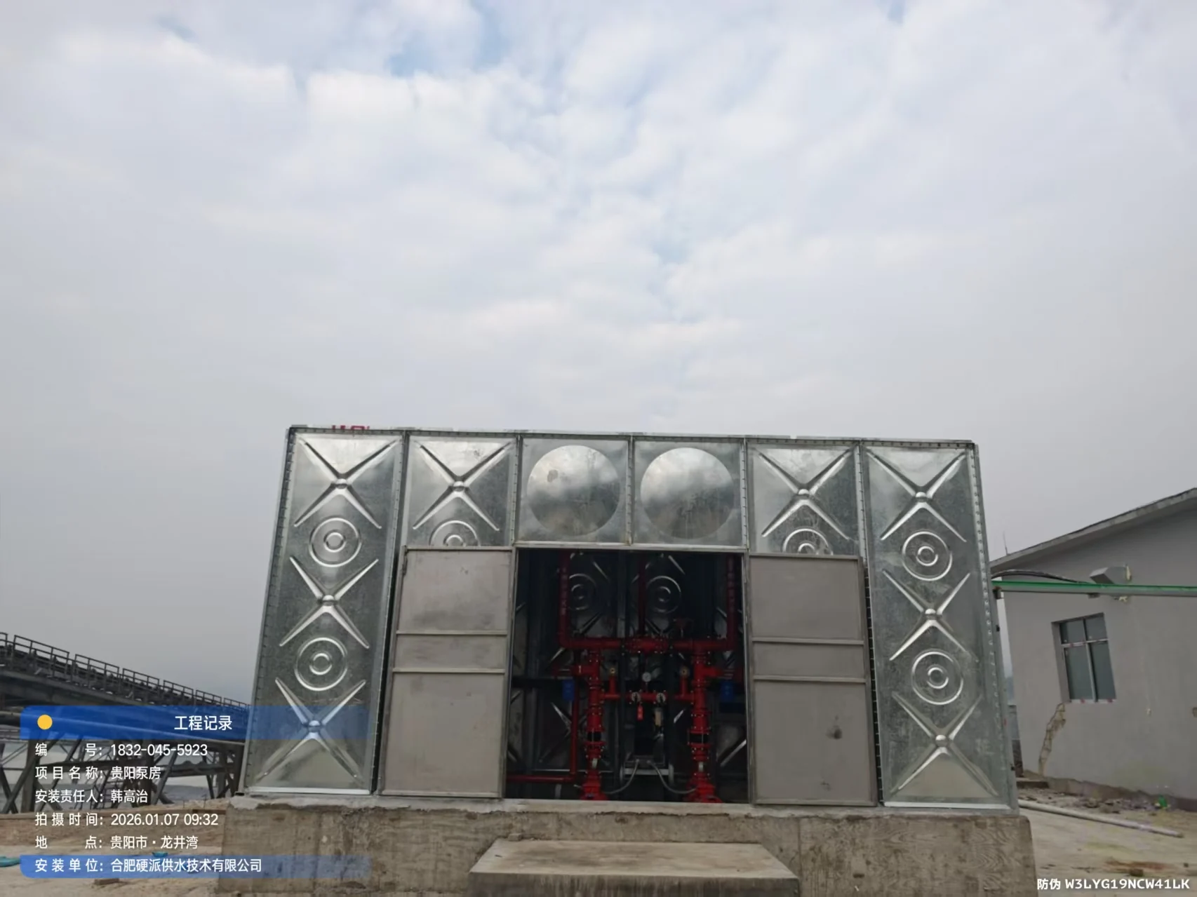
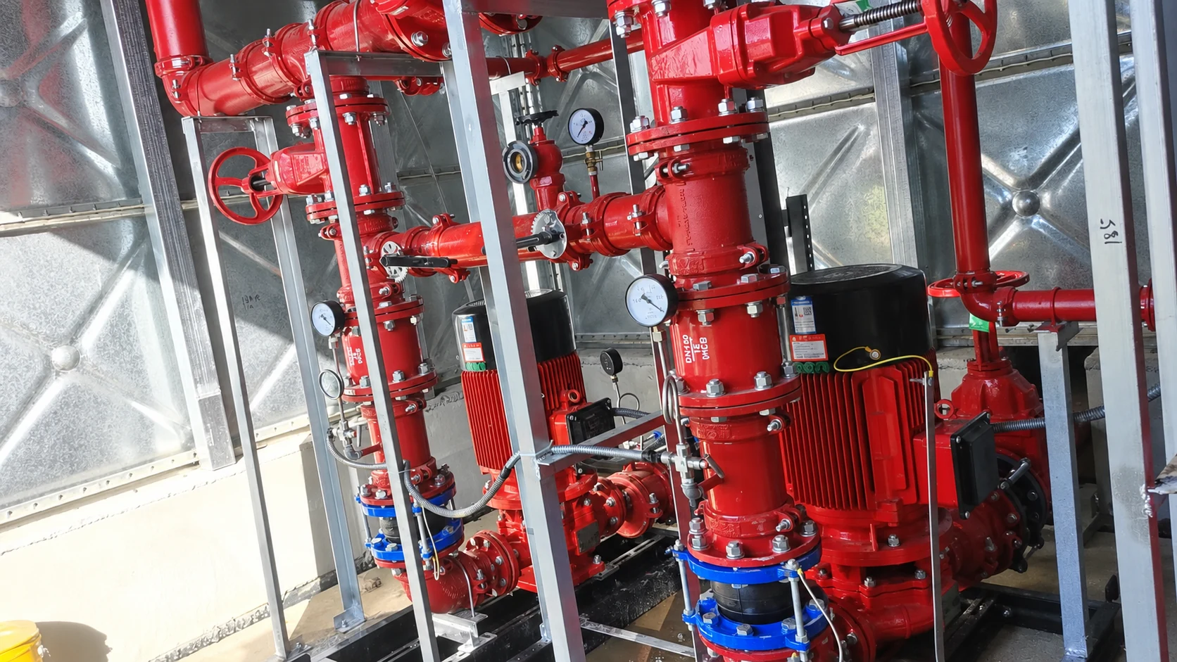
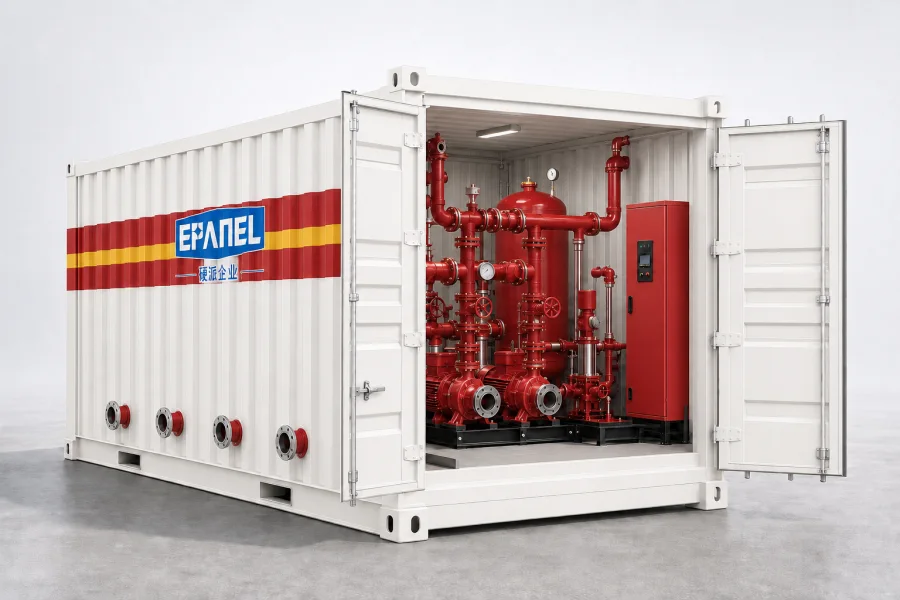
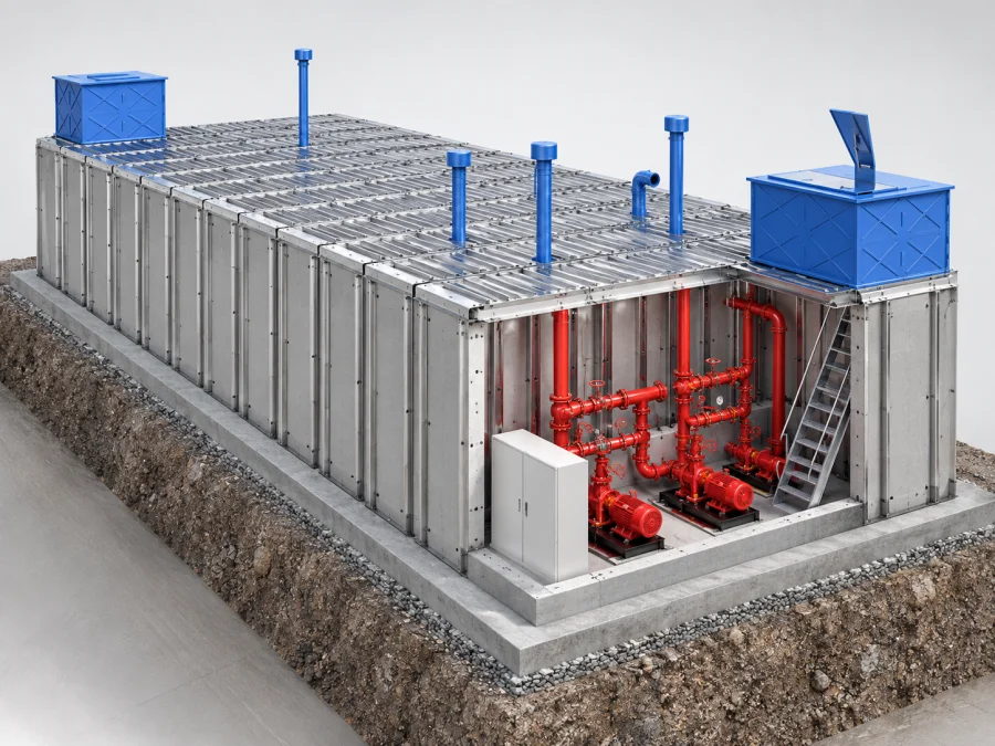
Ground firefightingBox pump integrated pump station
Integrated into complete sets, allowing fire water supply to be implemented in an orderly manner.
Integrate fire water tanks, pump units, pipelines and electrical controls into the ground space. From equipment selection to on-site installation, every connection is planned.
Organize device configurations from a system perspective
02 / ABOVE GROUND
Centralized layout of ground space
Taking into account installation, inspection and maintenance
03 / CONFIGURATION
Deepen the plan around the project
Connecting water storage needs to site conditions
01 / SYSTEM COMPONENTS
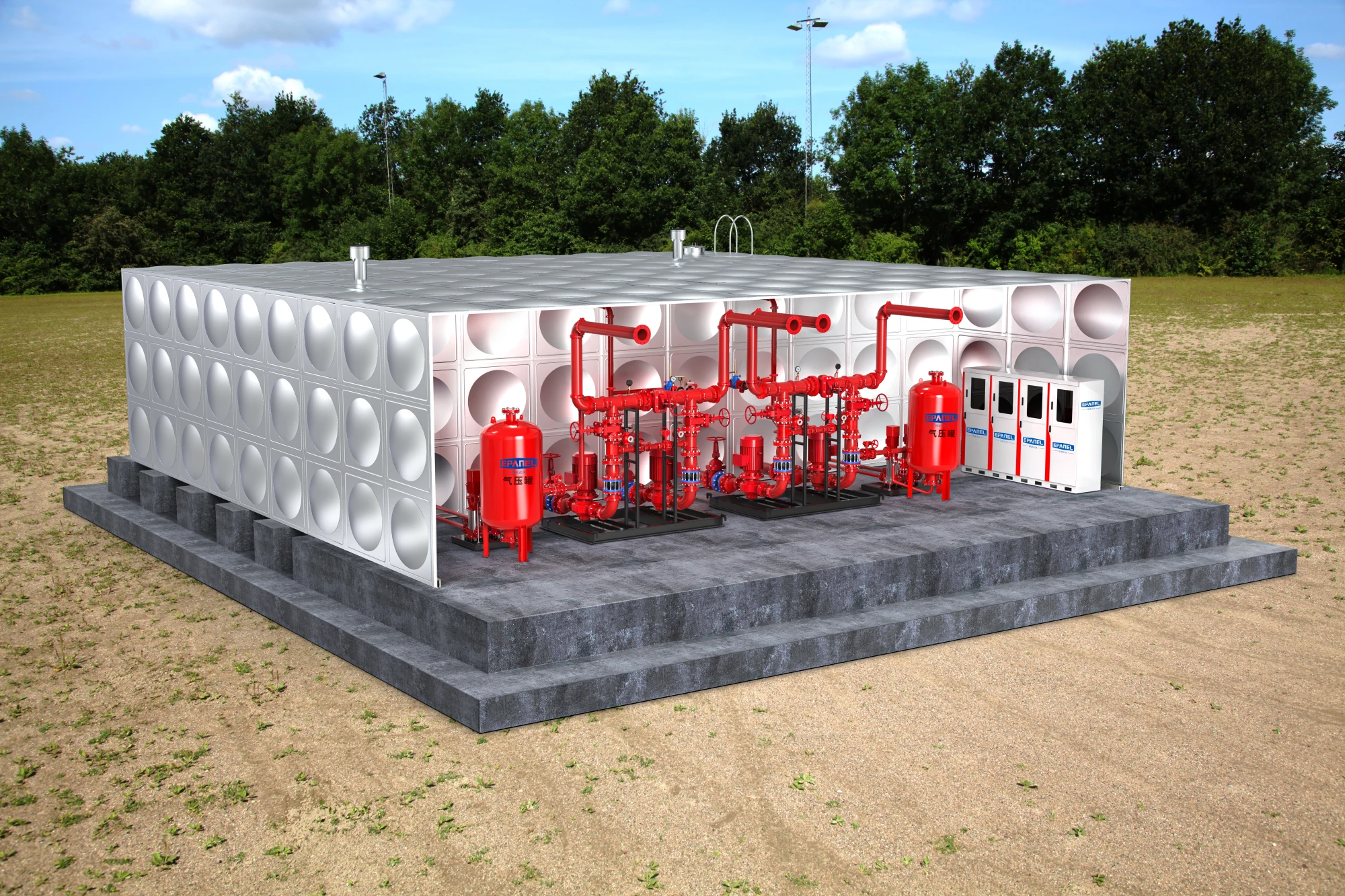
a pumping station, The four units work together.
Following the system idea of complete sets of fire pump stations, Let water storage, water supply, connection and control form a complete solution.
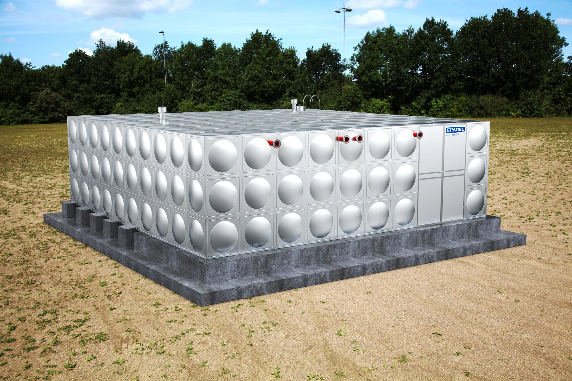
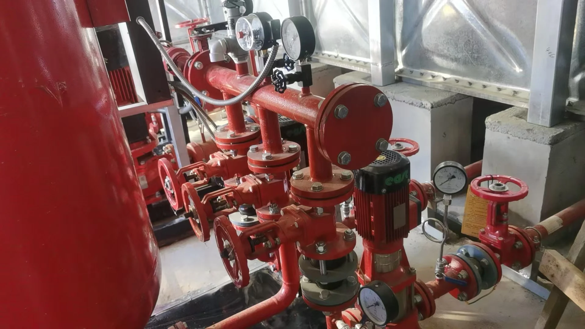
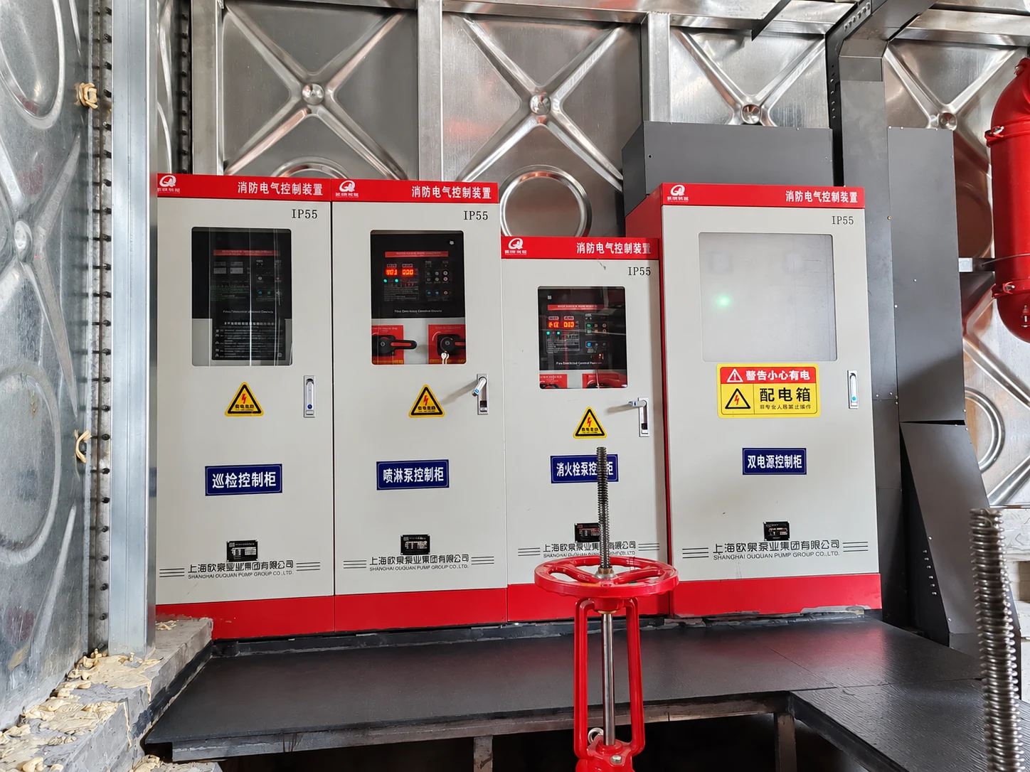
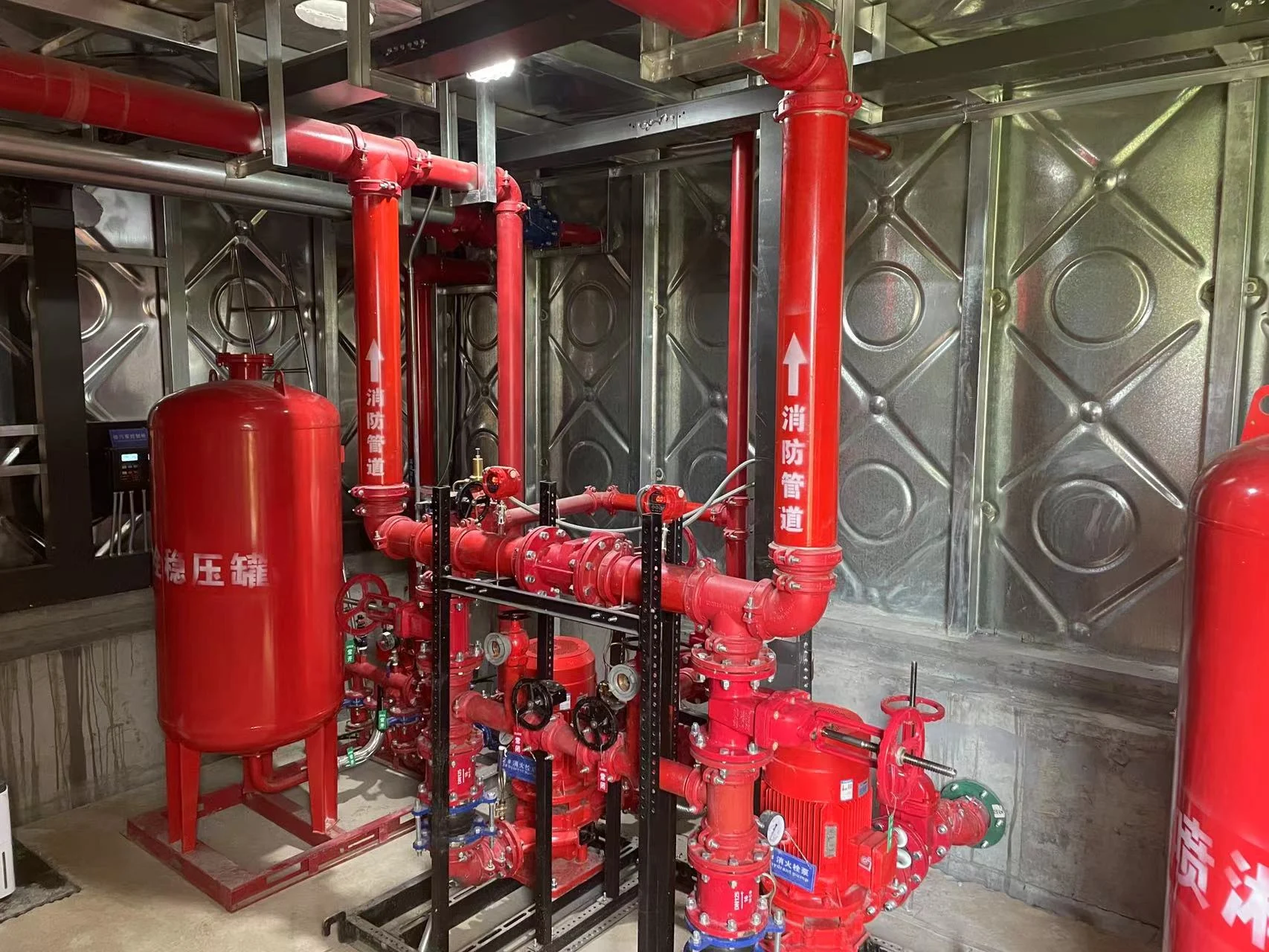
Water tank and pump room · Product rendering PRODUCT RENDERFirefighting unit · Overall layout rendering PRODUCT RENDERPipeline valve group · Overall layout rendering PRODUCT RENDERElectrical control · Overall layout rendering PRODUCT RENDER
01
FIRE WATER STORAGE
Consider water storage and foundation together.
The prefabricated box and pump room are arranged in coordination, and the plan is deepened around the effective water storage capacity, water inlet and outlet interfaces and maintenance conditions. The water tank material, plate type, support and sealing method are confirmed according to the project.
Effective volume/level monitoring/overflow and emptying
02
FIRE PUMP SET
Starting from the pump unit, organize each water supply.
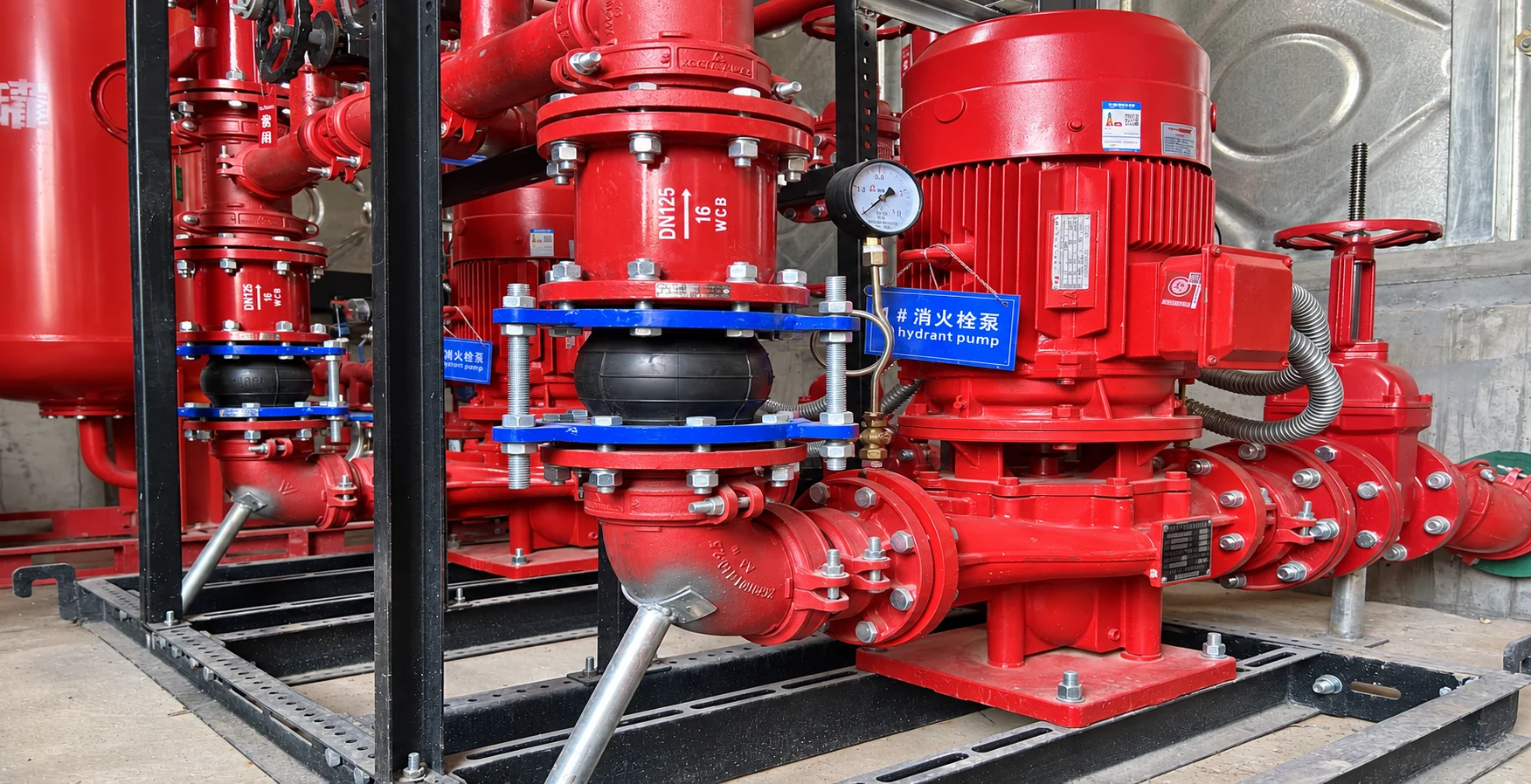
Fire pump units, voltage stabilizing devices and supporting pipelines are centrally arranged. Determine the pump unit configuration and backup methods for fire hydrants, sprinklers and other systems based on the design flow, head and system zoning.
Flow and head / Main and backup configuration / Voltage stabilizing device
03
PIPING & VALVES
Every connection is easy to check.
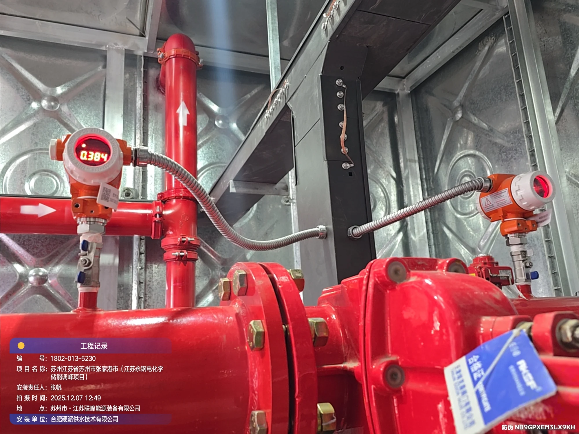
Coordinate water absorption, water outlet, test and drainage pipelines, and arrange valves, instruments and supports according to the interface direction. Reserve space for valve operation and equipment disassembly and assembly, so that on-site maintenance can be carried out in an orderly manner.
Interface connection / valve operation / maintenance space
04
ELECTRICAL CONTROL
Make the device status clearly visible.
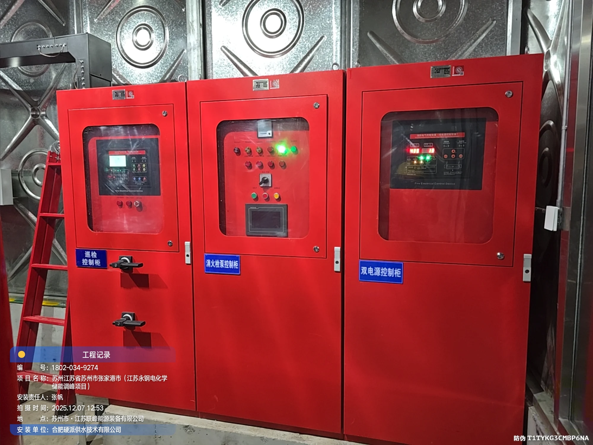
Configure fire control, inspection and power supply cabinet groups based on project design, and coordinate liquid level, pressure, operating status and alarm signals. The control logic, power supply and linkage interface are confirmed in the deepening stage.
Control cabinet group/signal feedback/linkage interface
From the water tank to the bottom foundation, Choose a construction that suits the site.
With or without a base plate, both options have their own emphasis. Determined based on civil engineering conditions, scope of supply and maintenance requirements.
A / WITH BOTTOM PLATE
Water tank with floor
The box itself forms a complete water storage boundary
The bottom plate, side plates and top plate together form the box, and the foundation is responsible for load-bearing and leveling. Suitable for projects that emphasize the complete delivery of the box and wish to clarify the equipment sealing responsibilities.
Pay attention to floor joints, support spacing and sealing nodes
Reserve bottom inspection, emptying and cleaning conditions
Organize full water test and delivery inspection based on plan
B / WITHOUT BOTTOM PLATE
Bottomless water tank
The water tank and civil engineering jointly organize the bottom interface
The bottom working interface is formed through foundation, water stop and related waterproof nodes. It is suitable for projects with sufficient civil engineering cooperation and the ability to coordinate equipment and foundation design.
Confirm foundation flatness, elevation and settlement control in advance
Clarify the construction scope of water-stopping, anti-seepage and drainage nodes
Coordinated inspection of equipment, civil engineering and waterproofing interfaces
Compare solutions · Clarify delivery boundaries
comparison item
There is a floor plan
No floor plan
water storage boundary
Composed of box bottom plate and side plates
The interface between the box and the bottom of the civil construction is composed of
basic coordination
Loading, leveling and support conditions
Bearing, leveling, anti-seepage, water stopping and drainage
Manufacturing and installation
There are many bottom plate materials and sealing processes
Box materials can be reduced, and on-site collaboration requirements are higher
Basic accuracy, interface water stop, drainage path
The effective volume, water absorption conditions, structure and foundation bearing capacity all need to be reviewed in conjunction with the project design; the specific scope of supply and technical parameters are subject to the confirmed plan.
03 / FROM DESIGN TO SITE
Let the equipment plan, Really come to the project site.
Electrical, foundation, and plumbing are considered together with routine maintenance. From preliminary condition confirmation to installation, commissioning and data delivery.
Enclosure, maintenance and foundation layout · Product rendering
01Foundation and site +
Confirm the site size, foundation load, elevation, flatness and settlement conditions, and coordinate equipment transportation, maintenance entrances and site drainage.
02Electrical and Control +
Confirm the power supply conditions, cabinet group layout, grounding and line laying, and clarify the interfaces such as fire protection linkage, liquid level and operation feedback.
03Pipeline and environment +
Determine the water inlet and outlet interfaces and pipeline supports, and consider thermal insulation, antifreeze, ventilation, lighting and maintenance access according to the site environment.
04Commissioning and delivery +
Organize full water inspection, equipment debugging and system linkage according to project design, and check signs, valve list and usage and maintenance information.
04 / REAL PROJECTS
In the real scene, See product details.
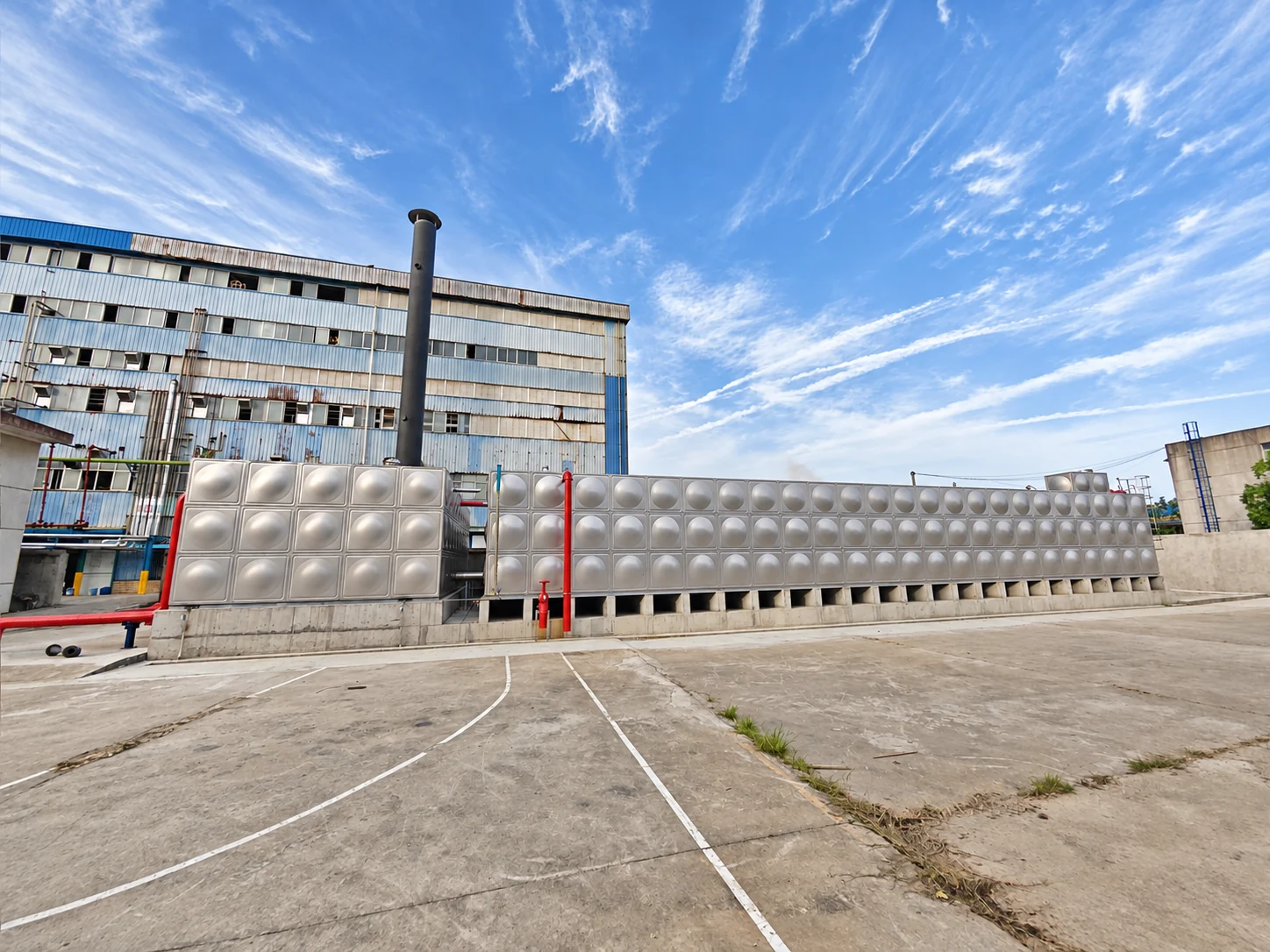
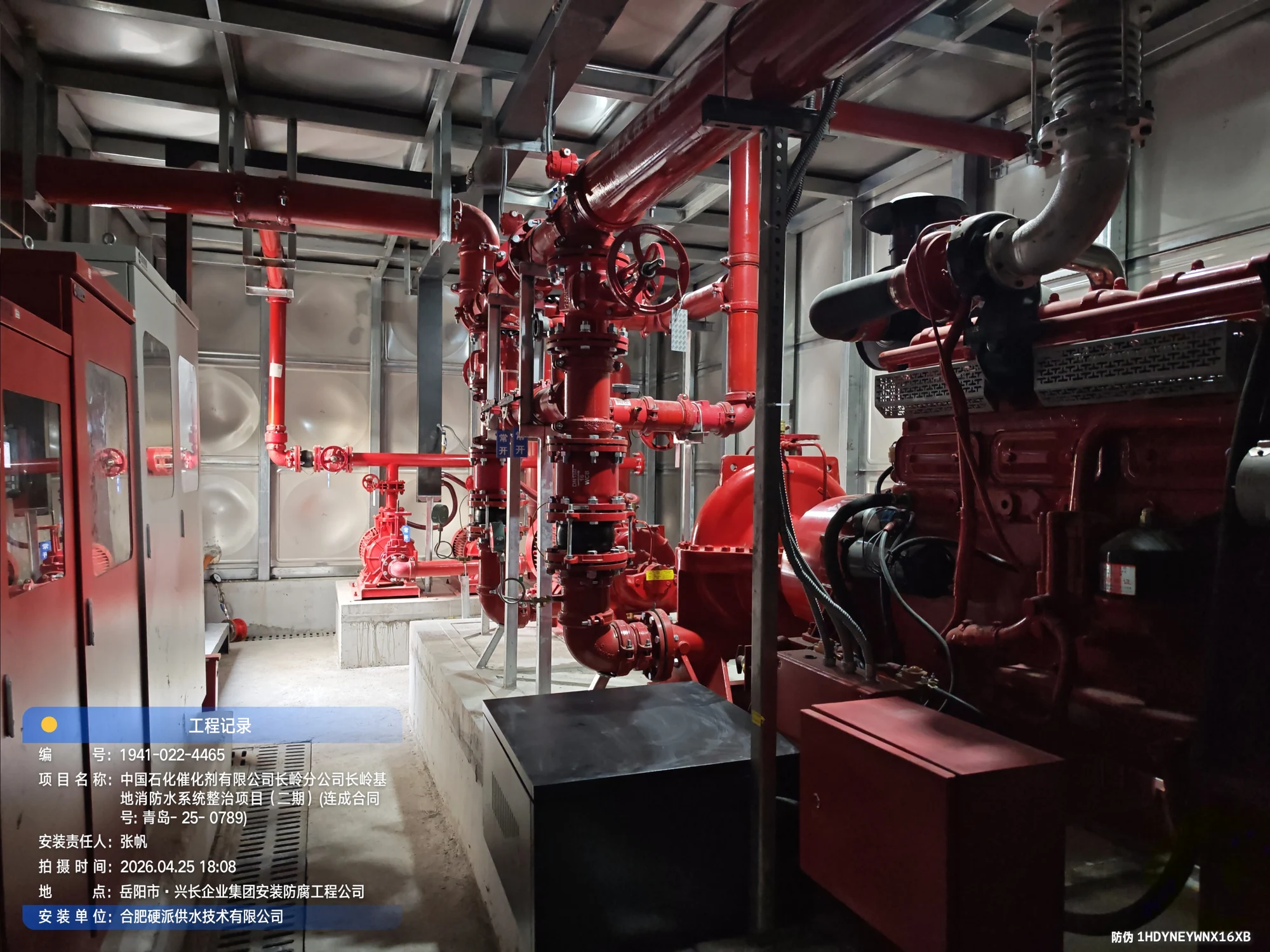
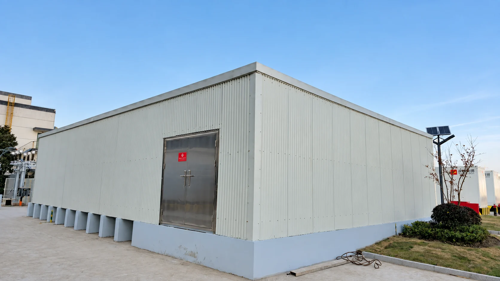
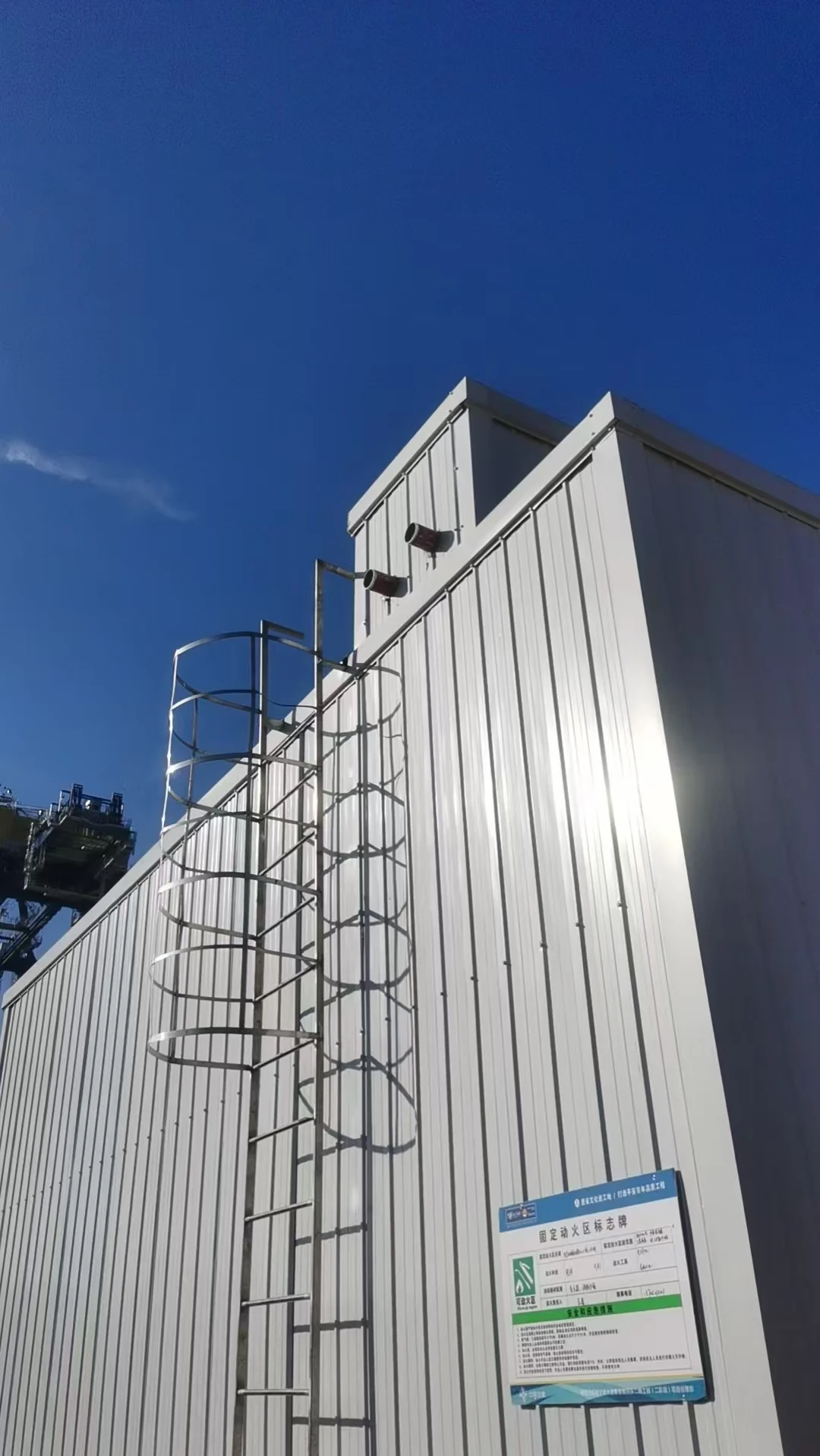
From the overall appearance, to the pump unit, piping and controls. For the same project, you can see on-site details from multiple angles.
Pause when the mouse is hovering or the keyboard is focused · Switch left and right arrow keys · Swipe to browse · Click to view a larger image
The pictures are from real projects, and some covers have been optimized for brightness and color; the newly added photos retain the original images. Configurations vary from project to project.
EPANEL / ENGINEERING SUPPORT
The next fire pump station, Start with your project requirements.
Provide the project purpose, effective water storage capacity, design flow and head, and site plan, At the same time, connect the equipment configuration with the site conditions.


 Back